Porous Epoxy Nanocomposite Monoliths

Pending Publication Date: 2022-05-26
RUTGERS UNIVERSITY
View PDF0 Cites 0 Cited by
  • Summary
  • Abstract
  • Description
  • Claims
  • Application Information

AI Technical Summary

Benefits of technology

[0046]The matrix material may have a variety of properties and characteristics and may be present in the mixture in various amounts. For example, according to various embodiments, the matrix material may be selected from a polymer, an oligomer, and combinations thereof. The matrix material may be a resin such as a photocrosslinking or photopolymerizing resin, a thermally crosslinking resin, a vitrimer resin, or a thermoplastic resin. The matrix material may be an epoxy. Vitrimers are a class of plastics, which are derived from thermosetting polymers (thermosets) and are very similar to them. Vitrimers consist of molecular, covalent networks, which can change their topology by thermally activated bond-exchange reactions. The matrix material may, for example, be a multi-part epoxy, such as a 2-part epoxy. According to various embodiments, the mixture may include an amount of the matrix material within a range having a lower limit and/or an upper limit. The range may include or exclude the lower limit and/or the upper limit. The lower limit and/or upper limit can be selected from about 5, 6, 7, 8, 9, 10, 11, 12, 13, 14, 15, 16, 17, 18, 19, 20, 21, 22, 23, 24, 25, 26, 27, 28, 29, 30, 31, 32, 33, 34, 35, 36, 37, 38, 39, and 40% by mass based on the total mass of the mixture. For example, according to certain embodiments, the mixture may include from about 10 to about 30% by mass of the matrix material, or any combination of lower limits and upper limits described. According to various embodiments, the mixture may include the matrix material in an amount within a range having a lower limit and/or an upper limit. The range may include or exclude the lower limit and/or the upper limit. The lower limit and/or upper limit can be selected from about 5, 6, 7, 8, 9, 10, 11, 12, 13, 14, 15, 16, 17, 18, 19, 20, 21, 22, 23, 24, 25, 26, 27, 28, 29, 30, 31, 32, 33, 34, 35, 36, 37, 38, 39, 40, 41, 42, 43, 44, 45, 46, 47, 48, 49, and 50% by volume based on the total volume of the mixture. For example, according to certain embodiments, the mixture comprises the matrix material in an amount of from about 10 to about 40% by volume based on a total volume of the mixture, or any combination of lower limits and upper limits described.
[0047]The porogen may have a variety of properties and characteristics and may be present in the mixture in various amounts. For example, according to various embodiments, the porogen may be an oil. The oil may be any suitable oil, including one selected from vegetable oil, petroleum oil, silicone oil, and combinations thereof. According to various embodiments, the mixture may include the porogen in an amount within a range having a lower limit and/or an upper limit. The range may include or exclude the lower limit and/or the upper limit. The lower limit and/or upper limit can be selected from about 10, 11, 12, 13, 14, 15, 16, 17, 18, 19, 20, 21, 22, 23, 24, 25, 26, 27, 28, 29, 30, 31, 32, 33, 34, 35, 36, 37, 38, 39, 40, 41, 42, 43, 44, 45, 46, 47, 48, 49, 50, 51, 52, 53, 54, 55, 56, 57, 58, 59, 60, 61, 62, 63, 64, 65, 66, 67, 68, 69, and 70% by mass based on the total mass of the mixture. For example, according to certain embodiments, the mixture may include the porogen in an amount of from about 20 to about 60% by mass, or any combination of lower limits and upper limits described. According to various embodiments, the mixture may include the porogen in an amount within a range having a lower limit and/or an upper limit. The range may include or exclude the lower limit and/or the upper limit. The lower limit and/or upper limit can be selected from about 25, 26, 27, 28, 29, 30, 31, 32, 33, 34, 35, 36, 37, 38, 39, 40, 41, 42, 43, 44, 45, 46, 47, 48, 49, 50, 51, 52, 53, 54, 55, 56, 57, 58, 59, 60, 61, 62, 63, 64, 65, 66, 67, 68, 69, 70, 71, 72, 73, 74, and 75% by volume based on the total volume of the mixture. For example, according to certain embodiments, the mixture may include the porogen in an amount of from about 30 to about 70% by volume based on a total volume of the mixture, or any combination of lower limits and upper limits described.
[0048]The interfacial compatibilizer may have a variety of properties and characteristics and may be present in the mixture in various amounts. For example, according to various embodiments, the interfacial compatibilizer may include an epoxidized oil. The epoxidized oil may be any suitable epoxidized oil, such as one selected from an epoxidized soybean oil, an epoxidized alkane, epoxy silicone, and combinations thereof. According to various embodiments, the mixture may include the interfacial compatibilizer in an amount within a range having a lower limit and/or an upper limit. The range may include or exclude the lower limit and/or the upper limit. The lower limit and/or upper limit can be selected from about 1, 2, 3, 4, 5, 6, 7, 8, 9, 10, 11, 12, 13, 14, 15, 16, 17, 18, 19, 20, 21, 22, 23, 24, and 25% by mass based on the total mass of the mixture. For example, according to certain embodiments, the mixture may include the interfacial compatibilizer in an amount of from about 1 to about 10% by mass, or any combination of lower limits and upper limits described. According to various embodiments, the mixture may include the interfacial compatibilizer in an amount within a range having a lower limit and/or an upper limit. The range may include or exclude the lower limit and/or the upper limit. The lower limit and/or upper limit can be selected from about 1, 2, 3, 4, 5, 6, 7, 8, 9, 10, 11, 12, 13, 14, 15, 16, 17, 18, 19, 20, 21, 22, 23, 24, 25, 26, 27, 28, 29, and 30% by volume based on the total volume of the mixture. For example, accordin

Problems solved by technology

However, these methods require high temperature treatments or incur significant materials shrinkage.
For many applications, requiring specifically sized pores and/or channels, unpredictable shrinkage is a major problem.
All of these methods have serious limitations and drawbacks.
One problem is that the overall pore structure is highly linked to the shrinkage that occurs during polymerization.
Another issue is that the final structures all have the surface chemistry of the photoresist unless further post-treatment is applied.
One sol

Method used


Image

  • Porous Epoxy Nanocomposite Monoliths
  • Porous Epoxy Nanocomposite Monoliths
  • Porous Epoxy Nanocomposite Monoliths

Examples


Example

Examples 1-2

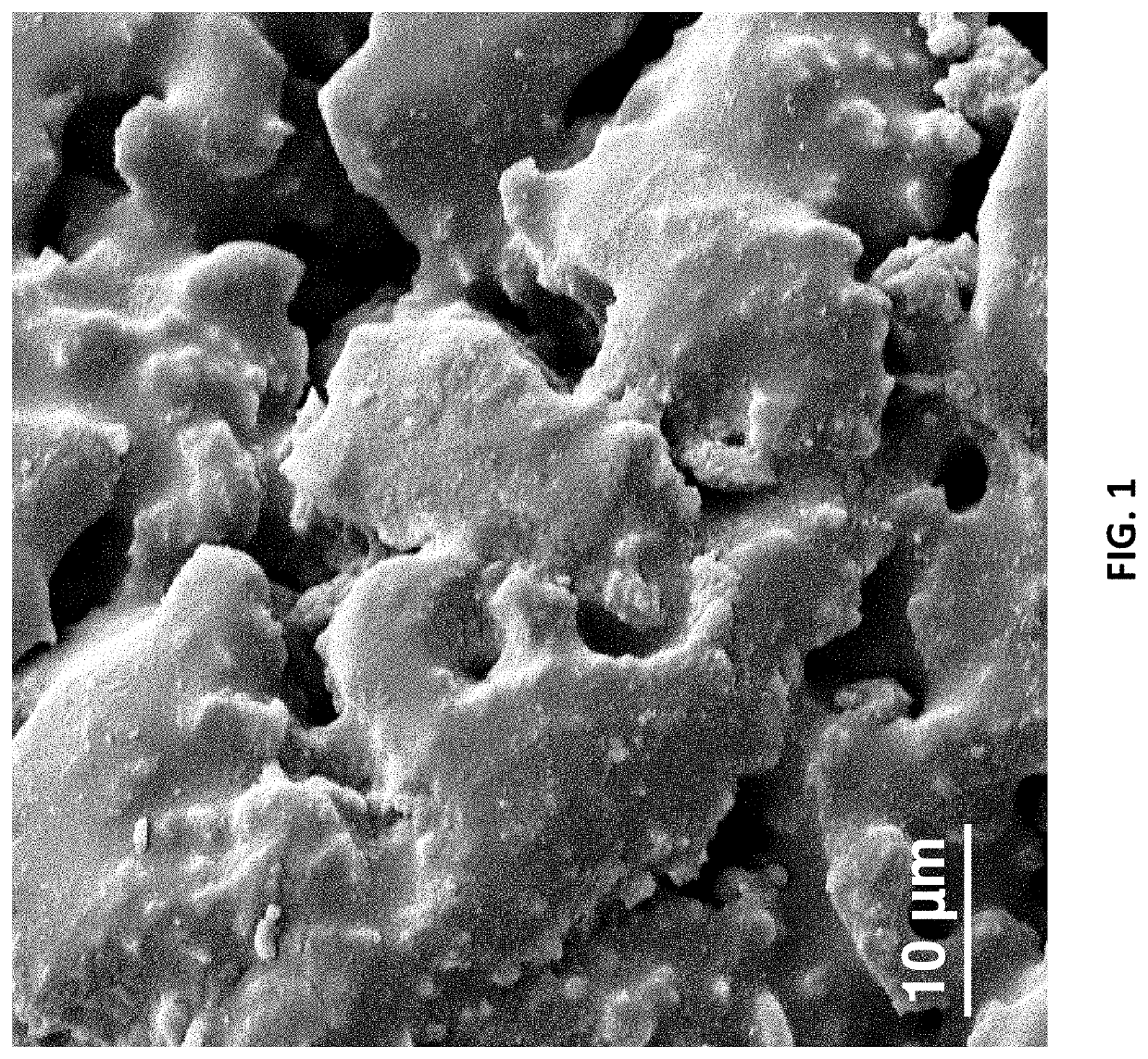
[0070]A purpose of Examples 1 and 2 is to demonstrate results obtained, according to various embodiments. More specifically, these examples show results obtained at a transition of mixed to bicontinuous of a monolith created with a plurality of activated carbon particles having an average size of about 100 nm (obtained from Skyspring Nanomaterials) after removal of the oil. While both examples are bicontinuous, the morphological differences are stark despite the main compositional shift being in the porogen phase, indicating the importance of all components in the process. Molding into micro or nanostructures requires a certain range of viscosity where viscous forces are much greater in magnitude than capillary forces. Further, the long lifetime of the homogenization allows for structures that are of a nearly arbitrary scale.

Example

Example 1

[0071]First, the specific amount of two-part epoxy, particles, epoxidized oil, and vegetable oil are placed in a mixing cup. In a specific example shown in FIG. 1, the composite was made of 9.52 wt % Epon 828 (Hexion Inc.) epoxy resin, 9.52 wt. % Versamid 125 (Gabriel Performance Products) curing agent, 4.77 wt % epoxidized soybean oil (from Arkema Inc.), 44.62 wt % canola oil, and 28.58 wt % activated carbon (100 nm, Skyspring Nanomaterials). The components were speed mixed for 1 minute in a Flacktek Speedmixer at 3500 RPM. After the composite gets cured, to make it porous, the porogen (canola oil) was removed by submerging the monolith of the composite into acetone bath for at least 1 day. Finally, the porous composite was dried in air.

[0072]FIG. 1 is an example according to various embodiments, illustrating a scanning electron microscope (SEM) image of monoliths after porogen removal. The revised composition of the monoliths after porogen removal is: 18.18 wt % Epon 828 ...

Example

Example 2

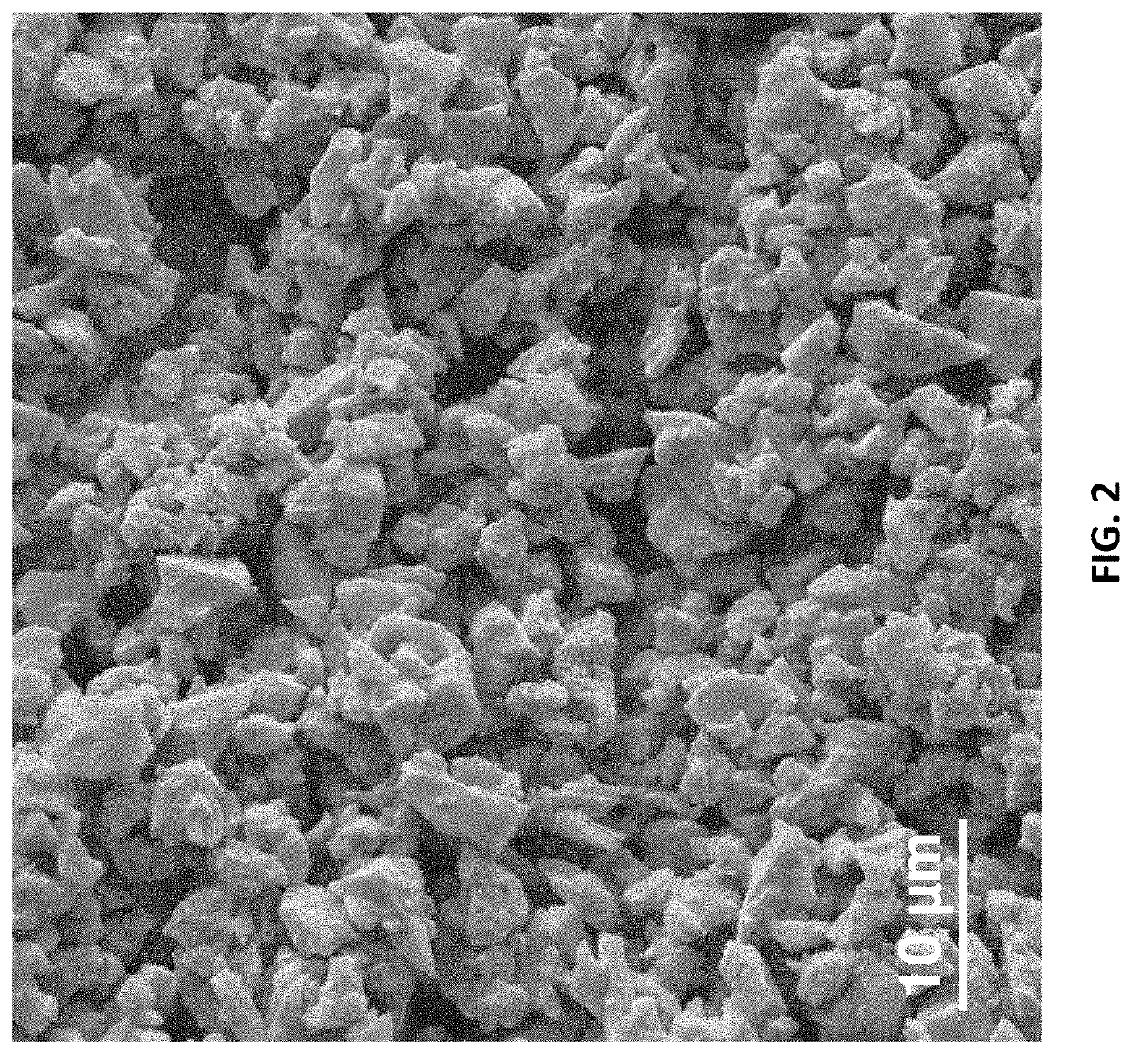
[0073]First, the specific amount of two-part epoxy, particles, epoxidized oil, and vegetable oil are placed in a mixing cup. In a specific example shown in FIG. 1, the composite was made of 8.00 wt % Epon 828 (Hexion Inc.) epoxy resin, 8.00 wt. % Versamid 125 (Gabriel Performance Products) curing agent, 4.00 wt % epoxidized soybean oil (from Arkema Inc.), 40.00 wt % canola oil, and 40.00 wt % activated carbon (100 nm). The components were speed mixed for 1 minute in a Flacktek Speedmixer at 3500 RPM. After the composite gets cured, to make it porous, the porogen (canola oil) was removed by submerging the monolith of the composite into acetone bath for at least 1 day. Finally, the porous composite was dried in air.

[0074]FIG. 2 is an example according to various embodiments, illustrating a scanning electron microscope (SEM) images of monoliths after porogen removal. The revised composition of the monoliths after porogen removal is: 13.13 wt % Epon 828 (Hexion Inc.) epoxy resi...


PUM

PropertyMeasurementUnit
Fractionaaaaaaaaaa
Fractionaaaaaaaaaa
Percent by massaaaaaaaaaa

Abstract

Method of preparing a porous material includes preparing a mixture of from about 10 to about 30% by mass of a matrix material, from about 20 to about 60% by mass of a plurality of particles, from about 20 to about 60% by mass of a porogen, and from about 1 to about 10% by mass of an interfacial compatibilizer. The matrix material and the porogen may be selected so as to be phase separated in the mixture. The method may further include placing the mixture into a form; initiating a solidification of the matrix material during which the porogen remains nonvolatile and the matrix material and the porogen remain phase separated; and removing at least a portion of the porogen to obtain the porous material. Porous materials produced by the methods. Microfluidic channels produced by the methods.

Description

[0001]This application claims the benefit of U.S. Provisional Patent Application No. 62 / 823,921, filed Mar. 26, 2019, titled POROUS EPOXY NANOCOMPOSITE MONOLITHS, which is incorporated by reference herein in its entirety.FIELD OF THE INVENTION[0002]Various embodiments of the present invention relate generally to porous nanocomposites and more specifically to porous epoxy nanocomposite monoliths.BACKGROUND[0003]Porous materials are crucial for numerous applications, including energy conversion and storage, catalysis, tissue engineering, drug delivery, cell-makers, smart filtering, and photonics. Porous monoliths have proven useful as an alternative stationary phase material for diverse applications including liquid chromatography. A porous monolith can be defined as an object having a continuous solid phase that defines a plurality of internal channels extending through. A plethora of methods have been developed to fabricate porous monoliths. However, these methods require high tempe...

Claims


Application Information

Patent Timeline
IPC IPC(8): C08J9/00C08J9/28
CPCC08J9/0061C08J9/008C08J2363/00C08J2201/026C08J9/283C08J2201/0502C08J2201/052C08J2201/0543C08J2361/08C08J9/0066C08J2405/08C08J9/40
Inventor SINGER, JONATHAN P.HASAN, MOLLA
Owner RUTGERS UNIVERSITY
Why Eureka
Try Eureka