Shape memory polymer blend materials

Active Publication Date: 2018-12-27
UT BATTELLE LLC
0 Cites 3 Cited by

AI-Extracted Technical Summary

Problems solved by technology

However, the demand for such products is not large ...

Benefits of technology

[0012]In particular embodiments, the present disclosure reports a simple approach for programming electrical conductivity in a renewable shape memory material containing a conductive leathery skin composed of a layer of metallic nanoparticles. The combination of metallic layer and the material's unique shape fixing and recovery attribute permits cyclic programming and restoration of the devices' electrical conductivity at 20-50% strain amplitude and at 50° C.-100° C., which is significantly above the glass transition temperature (Tg) of the rubbery matrix. Low molecular weight lignin bio-polymers with different molecular architectures and functionalities have herein been incorporated into an acrylonitrile-butadiene rubber to tune the composites' thermo-mechanical response. ...

Abstract

An object comprising: a blend of (i) a phenol-containing polymer and (ii) a nitrile butadiene rubber; wherein the phenol-containing polymer is present in an amount of at least 5 wt % and up to about 95 wt % by total weight of components (i) and (ii). The object may further contain an electrically conducting component dispersed within the blend or on a surface of the blend. Also described is a method of thermal-activated reversible mechanical deformation of the object by (i) deforming the object at a first temperature, which is at or above the glass transition temperature of the object, and applying a stress on the object; (ii) fixing the deformed state by cooling the object to a second temperature of no more than 0° C. while under stress, and removing the stress; and (iii) recovering the object to the original shape by raising the temperature of the object to the first temperature.

Technology Topic

Image

  • Shape memory polymer blend materials
  • Shape memory polymer blend materials
  • Shape memory polymer blend materials

Examples

  • Experimental program(1)

Example

[0051]In a first embodiment, the electrically conducting material is in the form of particles having a zerovalent metal composition. Some examples of zerovalent metals include, for example, silver (Ag), gold (Au), cobalt (Co), rhodium (Rh), iridium (Ir), nickel (Ni), palladium (Pd), platinum (Pt), copper (Cu), cadmium (Cd), aluminum (Al), and tin (Sn). The zerovalent metal particles may contain a single zerovalent metal, or may contain two or more zerovalent elements. In the case of two zerovalent metals, they may be present in the particle in a homogeneous manner (i.e., as an alloy), or in a heterogeneous manner, such as a core-shell arrangement. Particles of such elements are well known in the art. In a second embodiment, the electrically conducting material is in the form of electrically conducting particles, typically nanoparticles, of carbon. The conductive carbon particles may be, for example, any of the conductive carbon particles described above and as known in the art.
[0052]In another aspect, the present disclosure is directed to methods for producing the polymer blend material described above. In the method, at least (or only) the components (i) and (ii) are mixed and homogeneously blended to form the polymer blend material. If an electrically conducting material is to be incorporated within the blend, the electrically conducting material may also be mixed with components (i) and (ii) and all three components homogeneously blended. Any one of the components can be included in liquid form (if applicable), in solution form, suspension form, or in particulate or granular form. In the case of particles, the particles may be, independently, nanoparticles (e.g., at least 1, 2, 5, or 10 nm, and up to 20, 50, 100, 200, or 500 nm), microparticles (e.g., at least 1, 2, 5, or 10 μm, and up to 20, 50, 100, 200, or 500 μm), or macroparticles (e.g., above 500 μm, or at least or up to 1, 2, 5, 25, 50, 100, 500, or 1000 mm). Typically, if a polymeric component is provided in particle or granular form, the particles are melted or softened by appropriate heating to permit homogeneous blending and uniform dispersion of the components. The components can be homogeneously blended by any of the methodologies known in the art for achieving homogeneous blends of solid, semi-solid, gel, paste, or liquid mixtures. Some examples of applicable blending processes include simple or high speed mixing, compounding, extrusion, or ball mixing, all of which are well-known in the art. In some embodiments, the acrylonitrile-containing rubbers are in solid bale form and those could be cut into usable chunks using standard bale cutting tools. Those chunks of different sizes are mixed or blended with other component(s) in an internal mixer (such as Banbury mixer). In other embodiments, the acrylonitrile-containing rubbers are in latex form and those are mixed or blended with component(s) in a ball mill. In some other embodiments, the acrylonitrile-containing rubbers are in sheet form and the components are mixed in a two-roll mill.
[0053]By being “homogeneously blended” is meant that, in macro (e.g., millimeter) scale, no discernible regions of at least components (i) and (ii) exist. If a modifying agent, as discussed above, is included, all or a portion of the modifying agent may or may not remain in the solid (unmelted) phase, e.g., either in elemental state (e.g., carbon particles) or in crystalline lamella phase (e.g., polyethylene oxide). In other words, the homogeneous blend may possess a modified or compatibilized phase structure (not necessarily a single phase structure, but often with retained but shifted Tg associated with individual phases) for at least components (i) and (ii). The modified-phase structure generally indicates near homogeneous integration at microscale or near the molecular level without losing each component's identity. In the case of an additional non-homogeneous component, the instantly described polymer blend including components (i) and (ii) can be viewed as a “homogeneous matrix” in which the additional non-homogeneous component is incorporated. Preferably, all of the components retain their identity and components are well dispersed in the nanometer scale.
[0054]In some embodiments, the mixture being blended further includes a crosslinking (or curing) agent, which may be a radical or physical crosslinking agent. A particular example of a physical crosslinking or curing agent is sulfur. The radical crosslinking agent is any substance that produces radicals to effect crosslinking of component (i) and/or (ii) either during the blending process and/or subsequently during a conditioning process, activation process, curing process, and/or shape-forming process. The radical crosslinking agent may decompose under thermal or radiative exposure to form reactive radicals. The radical crosslinking agent may be, for example, any of the radical polymerization initiators known in the art. In particular embodiments, the radical crosslinking agent is an organic peroxide compound. Some examples of organic peroxide compounds include dicumyl peroxide (DCP), t-butyl peroxide, benzoyl peroxide, methyl ethyl ketone peroxide, and acetone peroxide. The radical crosslinking agent may alternatively be an inorganic peroxide compound, such as a peroxydisulfate salt. The radical crosslinking agent may or may not also be selected from non-peroxide radical-producing compounds, such as azo compounds (e.g., AIBN or ABCN), or a halogen (e.g., Br2 or I2). In some embodiments, radical crosslinking may be achieved by physical means, such as by exposure of the material to electron beam (e.g., Stelescu et al., The Scientific World Journal, 684047, 2014) or ultraviolet (UV) radiation (e.g., Naskar et al., Carbon, 43(5) 1065-1072, 2005) that generates free radicals for crosslinking of the components. Hydrocarbon polymers generate free radicals by exposure to electron beam radiation. In some embodiments, to facilitate UV crosslinking, the polymer blend may be further modified with acrylates and/or conjugated ketones (benzophenone derivatives) additives that generate free radicals when exposed to UV radiation. In other embodiments, any one or more specific types or general class of crosslinking or curing agents are excluded from the preparation process.
[0055]The process for preparing the polymer blend material can employ any of the weight percentages (i.e., wt %) of components provided in the earlier description of the polymer blend material. Moreover, during the process (i.e., during blending), certain ranges in processing temperature (i.e., during blending), shear rate, and processing time (i.e., duration of blending at a particular temperature) may be selected to produce a polymer blend material having particularly desirable physical characteristics. With respect to processing temperature, the blending process is generally conducted at a temperature of at least or above 100° C. and up to or less than 200° C., which may be a temperature of about, for example, 100° C., 110° C., 120° C., 130° C., 140° C., 150° C., 160° C., 170° C., 180° C., 190° C., or 200° C., or a temperature within a range bounded by any two of the foregoing values. With respect to the shear rate (which is related to the mixing speed in rpm), the blending process is generally conducted at a shear rate of at least or above 10 s−1 and up to or less than 1000 s−1, which may be a shear rate of about, for example, 10, 20, 30, 40, 50, 100, 150, 200, 250, 300, 350, 400, 500, 600, 700, 800, 900, or 1000 s−1, or a shear rate within a range bounded by any two of the foregoing values. The mixing rate (in rpm) corresponding to the foregoing shear rate range is approximately 1-150 revolutions of the blades per minute. With respect to processing time, the blending process preferably employs a processing time (time during blending at a particular temperature and shear rate) of at least or above 5 minutes and up to or less than 45 minutes, which may be a processing time of about or at least, for example, 10, 15, 20, 30, 45, 60 minutes, or a time within a range bounded by any two of the foregoing values.
[0056]The polymer blend material is typically subjected to a shape-forming process to produce a desired shape of the polymer blend. The shape-forming process can include, for example, extrusion molding, injection molding, compression molding, melt pressing, or stamping, all of which are well known in the art. In other embodiments, the polymer blend material is used in a printing process to form a shape containing the polymer blend material, wherein the printing process can be, for example, a rapid prototyping (RP) process known in the art, such as a fused deposition modeling (FDM) or fused filament fabrication (FFF) process known in the art, which may also be collectively considered as 3D printing processes.
[0057]In another aspect, the present disclosure is directed to a method of thermal-activated reversible mechanical deformation of an object having the above-described shape memory characteristic. In the method, the object possesses a first (i.e., original) shape at a temperature below the glass transition temperature (Tg) of the object. The temperature below Tg is typically ambient (i.e., room) temperature. Room (ambient) temperature is generally understood to be a temperature within a range of 15-30° C., or more particularly, 20-25° C., or about 20° C. or 25° C. The Tg of the object (i.e., of the blend described herein) may be about or at least, for example, 10, 25, 30, 35, 40, 45, 50, 55, 60, 65, 70, 75, 80, 85, 90, 95, 100° C., or a Tg within a range bounded by any two of the foregoing values.
[0058]In a first step (i.e., step (i)), the object having an original shape at a temperature below Tg is raised in temperature to a first temperature, which is a temperature at or above the glass transition temperature of the object. When the object is raised to the first temperature, a stress is applied on the object to deform the object. The object at the first temperature is thus in a deformed state (i.e., has a different shape) relative to the original shape. In the case where the first temperature is above Tg, the first temperature remains below the melting point of the object (i.e., below the melting point of the blend of which the object is composed). The first temperature may be, for example, at least or no more than 5, 10, 15, 20, 25, 30, 40, or 50° C. above the Tg, provided the first temperature is below the melting point of the blend.
[0059]In a second step (i.e., step (ii)), the object in the deformed state at the first temperature is cooled to a second temperature of up to (no more than) or less than 0° C., while in the deformed state and while under the same applied stress mentioned above. The foregoing step functions to fix (i.e., program) the object to remain in the deformed state even when the applied stress is removed. Indeed, the second step includes removing the applied stress while at the second temperature with the object remaining in the deformed state. In some embodiments, the second temperature is no more than or less than −5, −10, 15, −20, −25, −30, −35, or −40° C.
[0060]In a third step (i.e., step (iii)), the object in the deformed state and not under an applied stress, is made to revert to its original shape by raising the temperature of the object to the first temperature. Thus, by raising the temperature of the object to the first temperature, the original shape of the object is recovered. This final step evidences a shape memory characteristic of the blend material. Moreover, after step (iii), the object possesses the ability to reversibly interconvert between the deformed and original shapes by being alternately subjected to fixing of the deformed state of the object according to step (ii) and recovering the original shape of the object according to step (iii).
[0061]In some embodiments, the thermal-activated reversible mechanical deformation is practiced on an object containing components (i) and (ii), but not an electrically conducting component (iii). In such embodiments, the shape memory object can be used in a host of applications where shape memory can play an important role. Some applications include, for example, sensors, actuators, artificial muscles, drug delivery systems, surgical and medical devices, self-healing structures, morphing structures, energy transfer devices, and self-assembling devices.
[0062]In other embodiments, the thermal-activated reversible mechanical deformation is practiced on an object containing components (i), (ii), and (iii). As discussed above, the electrically conducting material (component iii) may be within the blend (within the object) or as a coating on a surface of an object composed of the blend minimally containing components (i) and (ii) (i.e., wherein the blend containing minimally components (i) and (ii) defines a shape of the object). When the electrically conducting material is included in or on the object, deformation of the object results in a change in the electrical conductivity of the object. Since the object containing component (iii) changes in electrical conductivity with change in shape (which changes with temperature), the object can be used as a stress sensor, strain sensor, or electrical switch.
[0063]Examples have been set forth below for the purpose of illustration and to describe certain specific embodiments of the invention. However, the scope of this invention is not to be in any way limited by the examples set forth herein.
EXAMPLES
Synthesis and Analysis of an Acrylonitrile-Butadiene Polymer Blend
[0064]Overview
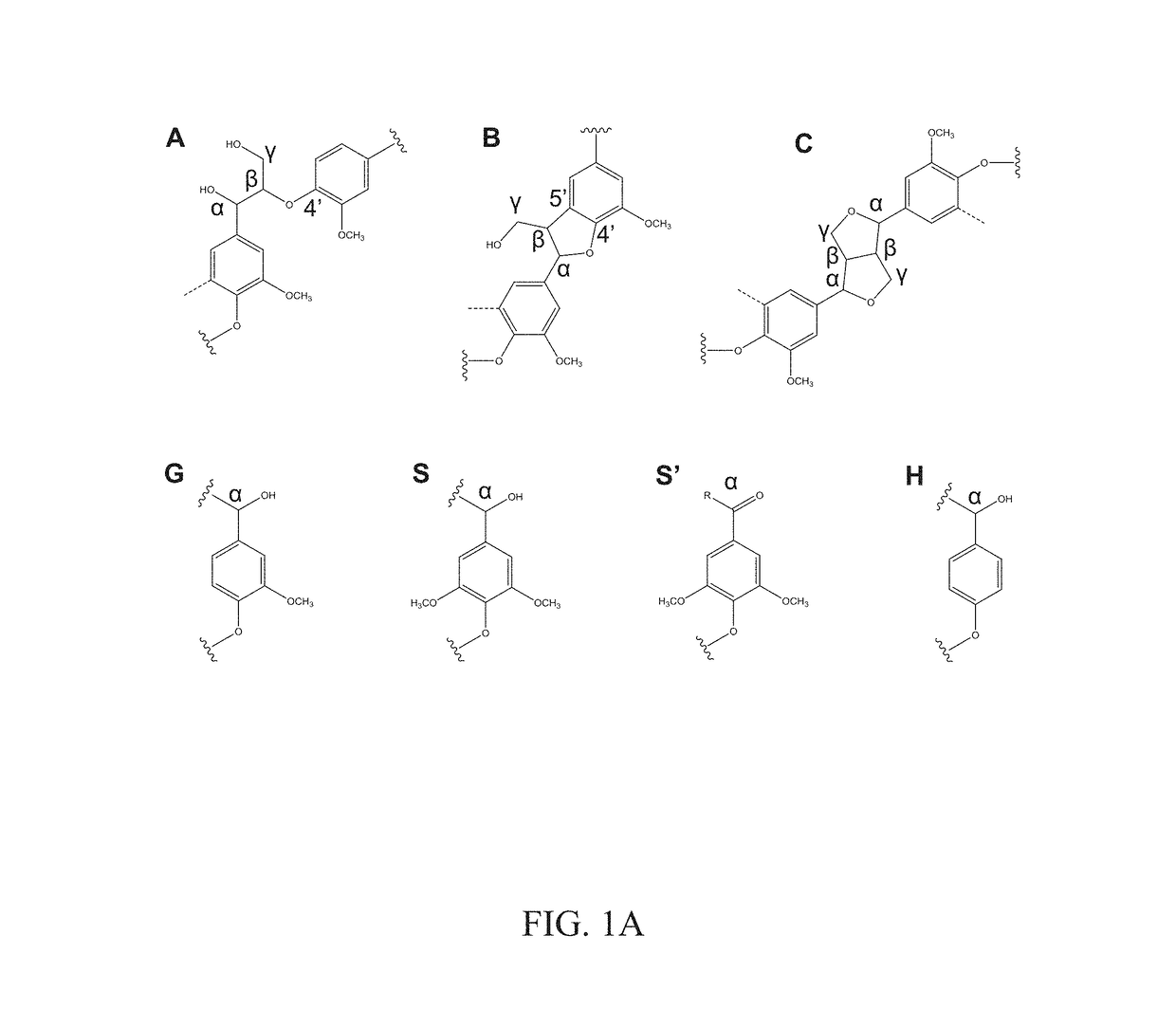
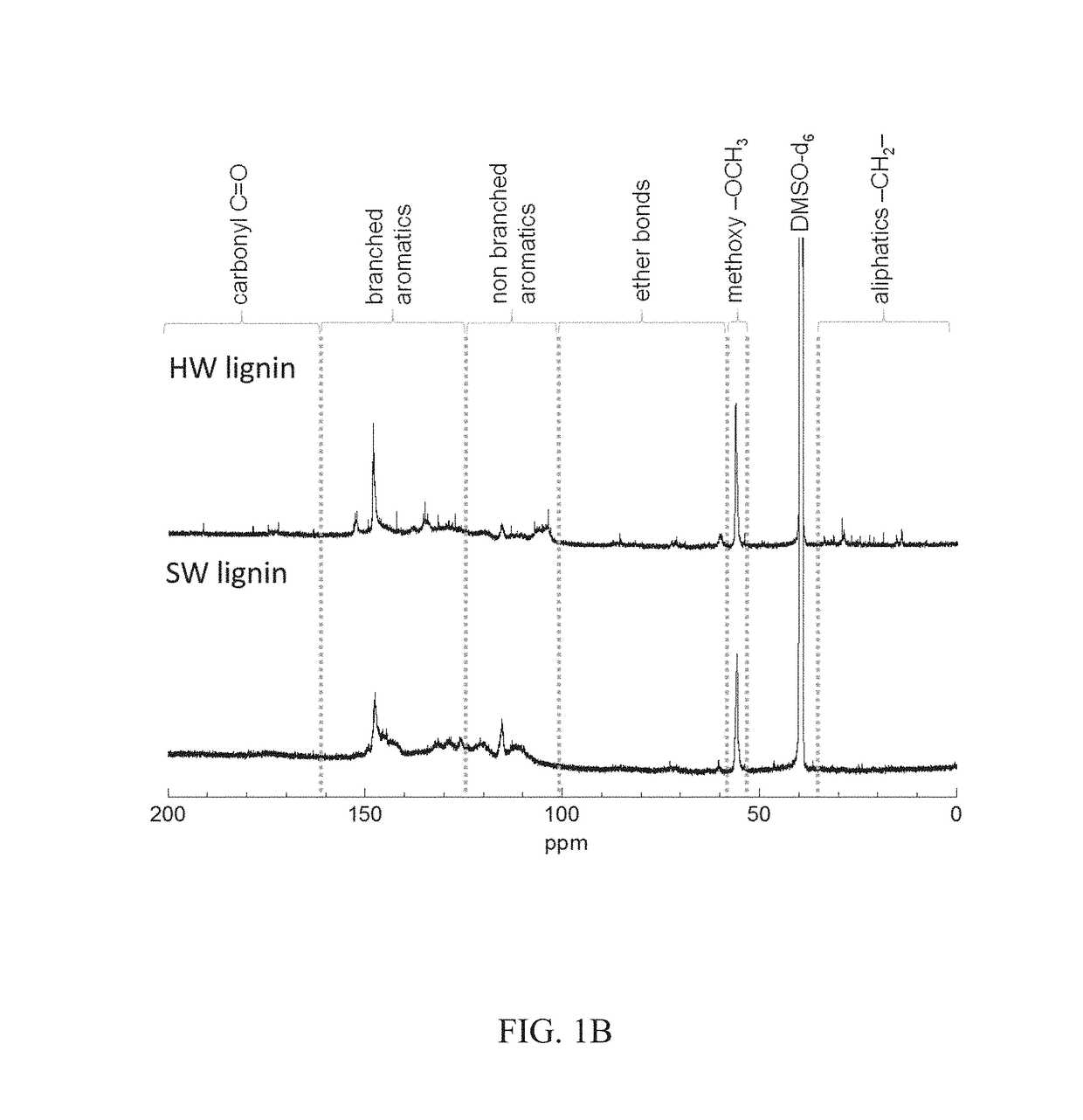
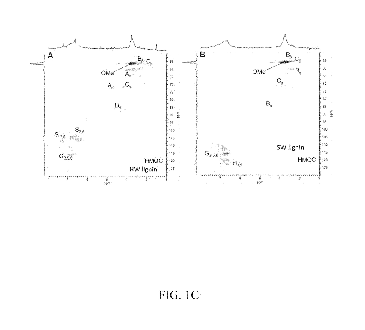
[0065]FIG. 1A depicts representative chemical structures of lignins. Lignin is an important component in plants by contributing to the stiffness of plant cell walls, accounting for ca. 15% to 40% dry weight (depending on the plant sources) and is the second most abundant (after cellulose) in plant biomass. It is often isolated as a byproduct from the pulping industry or biorefineries and used as a cheap feedstock for thermal energy recovery through combustion. The representative chemical structures of lignins used in these experiments were determined by 13C nuclear magnetic resonance (NMR) and two-dimensional (2D) 1H-13C heteronuclear multiple quantum coherence (HMQC) NMR spectroscopy. The measured 13C NMR spectra and 2D-NMR HMQC spectroscopy data are presented in FIGS. 1B and 1C. HW lignin contained significant β-O-4′ linkages (substructure A, shown in FIG. 1A), while this linkage was not detected in SW lignin. Both lignins contained β-5′ and β-β linkages (substructure B and C, respectively, in FIG. 1A). The measured data indicate that the guaiacylpropane unit (substructure G in FIG. 1A) is predominant in SW lignin, and is also present at lower concentrations in HW lignin. Additionally, the syringyl propane units (substructures S and S′ in FIG. 1A) were detected within HW lignin at concentrations higher than ‘G’ but were not observed in SW lignin, while p-hydroxyphenolpropane units (substructure H) were observed within SW lignin but not in HW lignin. In summary, HW contains a higher concentration of β-O-4′ and ‘G’ units, with no ‘H’; SW contains a higher concentration of ‘G’ and ‘H’ with no observed β-O-4′ linkages. The structure of the lignin used in the ABL formulation is significant in terms of its interaction with the nitrile rubber and the resulting shape-recovery effects.
[0066]The ability of a polymeric material to recover a permanent shape from a temporarily fixed deformation can be regulated by the chemical- and/or physical-crosslinking density of polymer molecular segments. After a polymeric material is deformed, it is stabilized by being quenched to a certain fixed temperature. Dynamic non-covalent bonds (such as hydrogen bonds) have been found to play a critical role in stabilizing the programmed (temporary) shape. Acrylonitrile-butadiene rubber (41 mol % nitrile content) (NBR41) possesses a good recoverable strain property after deformation. The elastic recovery of nitrile rubber arises from intermolecular crosslinking of nitrile groups during thermal processing (e.g., U.S. Pat. No. 4,885,096). However, a low glass transition temperature (−16.5° C.) of pristine NBR41 results in very low shape fixity (i.e., an inability to retain the deformed shape). In this study, lignin was used to enhance the glass transition temperatures (Tg) and the potential to store mechanical work through deformation that in turn improves shape fixity.
[0067]Synthesis
[0068]Acrylonitrile-butadiene rubber 41 (41 mol % nitrile content) and Organosolv hardwood and Kraft softwood were obtained commercially. Various softwood and hardwood lignin fractions, from 40 wt % to 60 wt %, were melt-mixed with the nitrile butadiene rubber (NBR-41) using a Brabender Plastic Corder equipped with a half-size (30 cc) mixing chamber and high shear twin roller blades. The rubber was loaded and mixed in the mixing chamber for two minutes at 90 rpm and 180° C. Lignin was then added, and mixing was continued with high shear mixing and reacting for a total of 60 minutes. After mixing, the samples were recovered and stored at room temperature for analysis. The lignin—NBR41 composite films were prepared by molding between two Teflon sheets at 190° C. for 20 minutes by use of a hydraulic press machine.
[0069]Shape Memory Characterization
[0070]Samples of pristine NBR41, SW- and HW-NBR41 with dimensions (3-5 mm×2 mm×50 mm) (W×T×L) were prepared for shape memory experiments. Three weight fractions, 40%, 50%, and 60%, of SW and HW lignins in NBR41 were characterized. The DMA—Q800 (TA instruments) was utilized to investigate the shape memory characteristics of these samples. The axial tension geometry was used. All measurements were conducted in a nitrogen atmosphere. The shape programming and recovery were investigated by deforming the materials at selected strain amplitudes, including 20%, 50%, and 100%. Also, two different programming temperatures, 50° C. and 100° C., were selected. The sample was loaded and attached on axial tension geometries at ambient temperature. After closing the oven chamber, the sample was purged with nitrogen and the temperature was ramped at 10° C./min to the tested temperature (50° C. or 100° C.). An isothermal step for two minutes was applied to equilibrate the sample before stretching to a desired strain amplitude. To fix (program) the temporary shape, the temperature was quickly cooled to −30° C. at a rate of 50° C./min. The applying force was released to a minimum value (0.001 N) before increasing the temperature back to the deforming temperature for recovering. An isothermal stage for 30 minutes at this temperature was applied for further recovering. The whole process of deforming, fixing, and recovering was repeated three times. The stress and modulus induced from deforming were measured as well. Repeatable shape recovery and fixity after three times of programming with very high strain amplitudes were determined and quantified. To visualize the programmable and recoverable shape properties, selected samples were manually stretched on a pre-heated hotplate then fixed by placing the sample on an aluminum-ice surface (i.e., a cup containing ice with aluminum foil covering the ice surface). The programmed (temporary) shapes were put on the pre-heated hotplate again to observe the recovery process. Recovery of the programmed shapes were recorded.
[0071]FIG. 2A is a graph that represents a typical cycle of deformation, fixing, and recovery for an ABL sample. The whole process and the associated deformation in networked structures are illustrated in FIG. 2B. Deformation of the networks in the ABL composite involves hydrogen bonds between the hydroxyl (—OH) groups of lignin molecules and the nitrile (—C≡N) groups of NBR41. The exceptional shape recovery and fixity of ABL was further employed to control the electrical conductivity for sensor applications.
[0072]FIG. 2C illustrates a method of programming the conductivity of the material by coating a layer of electrically conductive particles (e.g., Ag nanoparticles) on the shape-memory substrate. When the composite film was stretched, percolation and interconnections between the electrically conductive nanoparticles were decreased and broken, as illustrated by the dashed lines. Thus, electrical conductivity was substantially diminished or absent in the stretched material.
[0073]Thermomechanical Characteristics of ABL and its Networked Structure
[0074]The characteristics of the ABL materials were first investigated. The results of differential scanning calorimetry (DSC), as shown in FIG. 3A (vertically shifted for clear observation), evidenced a very low glass transition temperature (−16.5° C.) for pristine NBR41 and an increase in Tg by adding hardwood (HW) or softwood (SW) lignins at selected fractions. The degree of elevation in Tgs with respect to the pristine rubber was higher in SW-lignin-based ABL compositions. For example, the Tg was elevated from 17.1° C. to 27.8° C. in SW-lignin-based ABL composites for corresponding increases in lignin content from 40 wt % to 60 wt %; the elevation of Tg of HW-lignin-based ABL was 22.6° C. for a 60 wt % HW-lignin loading in NBR41. The well-known Flory-Fox equation was used for the thermal analysis. The results suggest that chemical crosslinks were created between lignin and NBR41. The 2D-NMR spectroscopy data of the two lignins revealed the predominance of guaiacylpropane units (substructure G) and p-hydroxyphenolpropane units (H) in SW-lignin, whereas the HW-lignin possesses fewer G units and no H units. The non-condensed G and H units indicate higher chemical reactivity and less steric hindrance around the phenolic hydroxyl group. The higher reactivity and reduced hindrance promote potential crosslinking reactions and the formation of hydrogen bonds between lignins and NBR41 under high-temperature shear mixing.
[0075]Unsaturated rubbers are known to create free radicals during thermal shear. The presence of double bonds (C═C), a symmetric stretch at ca. 1650 cm−1 within the nitrile butadiene rubber, promotes the chemical crosslinks with free radicals generated by thermally unstable linkages of lignin structural units. Since both SW and HW lignin have significant G substructure, they are expected to form chemical bonds. In addition, the thermally unstable linkages in HW lignin, such as β-O-4′ bonds and abundant methoxy (—OCH3) groups, are susceptible to form free radicals during high shear mixing cycles.
[0076]To investigate the molecular interactions of the ABL composites, frequency dependent rheological measurements at elevated temperatures were performed. The results, as provided in the graphs in FIGS. 3B and 3C, suggest that the dynamic shear storage modulus (G′) and the complex viscosity (η) of the pristine NBR41 are altered by the addition of various HW and SW lignin fractions. The ABL with SW-lignin-NBR41 composition exhibited strong improvement of G′ at a reference temperature of 190° C. in comparison with neat NBR41. A large region of frequency-independent G′ (a plateau region) was observed in the SW-lignin-based ABL composites, from 100 rad/s to a very low frequency (terminal region), 10−3 rad/s, which indicates the formation of a crosslinked structure. The increase in G′ of the SW-lignin-based ABL may be induced by the presence of the very rigid SW-lignin structure. Several orders of magnitude higher storage modulus of the pristine SW-lignin at 190° C. as compared to that of pristine HW-lignin confirms higher rigidity of the former than the latter.
[0077]Evidently, the HW-lignin-based ABL composition shows a considerable decrease in G′ of the NBR41 matrix at the low frequency. The drop in G′ of the NBR41 matrix after incorporation of HW lignin becomes very significant at high lignin content. As indicated in FIG. 3B, the slopes of G′ versus angular frequency in the terminal region of pristine NBR41 and the SW-based ABL approach zero, whereas the slopes are slightly higher for the HW-based ABL. This measured data suggests less intermolecular interaction occurs within the HW-based ABL in comparison to the others. Similarly, the comparison of a complex viscosity profile with angular frequency in FIG. 3C also indicates a lower degree of crosslink density and poorer intermolecular interaction in HW-based ABL than in the pristine NBR41 or the SW-based ABL. Again, the complex viscosity of ABL is strongly dependent on the lignin content and the nature of the lignin. It was also found herein that the melt viscosity of HW- and SW-lignin segments contributed significantly to the complex viscosity of the ABL composites. Moreover, the data in FIG. 3C exhibit no zero-shear viscosity, which evidences prevalence of a crosslinked or networked structure in the compositions.
[0078]The evidence indicates both physically and chemically networked structures. The physical crosslinks appear to be formed by hydrogen bonds within lignin and nitrile rubber molecules, while the chemical crosslinks appear to be the result of intrinsic networked structures of lignins along with entanglements and other thermally formed networks in nitrile rubber. The degree of chemical crosslinking between rubber and the lignin is apparently low; otherwise, its molding and thermal reprocessing, including rheological study of the molded specimens, would have been very difficult. Nonetheless, the formation of a slightly networked structure between the lignin and rubber was studied using swelling of the alloys in solvents (Bova, T. et al. Green Chemistry 2016, 18 (20), 5423-5437). It is noticed that the storage modulus and the complex viscosity of 60 wt % SW-based ABL slightly decreased with respect to the measured data of the 50 wt % SW-based ABL composite. SW lignin is very rigid even at a very high temperature (190° C.), as demonstrated by a very high melt storage modulus (over 30 MPa) and a high complex viscosity (over 4×10⁵ Pa·s). Most likely, a very high lignin loading, 60 wt %, and a high thermal shear (90 rpm) at 180° C. during the mixing could result in depolymerization of rigid SW-lignin. The ABL made with SW lignin was chosen for further work because of its ability to form a rigid networked structure.
[0079]Additionally, the measured results of thermogravimetric analysis (TGA) (see FIGS. 3D and 3E) suggest that the intermolecular interactions of SW lignin with NBR41 (including the possibility of crosslinking and formation of more hydrogen-bonded assemblies) are superior to those of HW lignin with the NBR41. The data in FIGS. 3D and 3E show different thermal stability behaviors of the investigated samples. Pristine NBR41 indicates the highest thermal degradation temperature, whereas both SW and HW lignins revealed very low thermal stability. However, by incorporating these two selected lignins into NBR41, their corresponding composites with NBR41 exhibit very different thermal stability characteristics. Although HW-lignin is thermally more stable than SW-lignin, the TGA thermograms demonstrate that the thermal stability of SW-lignin-based ABL is superior to that of the HW-lignin-based ABL. For example, the temperature associated with fixed mass loss (2 wt. %) is slightly higher for HW lignin (209° C.), than the SW-lignin (204° C.). However, as shown by the data in FIGS. 3D and 3E, after melt-mixing of these lignins with pristine NBR41, the ABL compositions exhibit an increase in temperature associated with 2 wt. % mass loss. This increase in specific degradation temperature is significantly higher for SW-lignin-based ABL (approximately 100° C.) than that of the HW-lignin-based ABL (ca. 40° C.). Most likely, the increase in molecular interactions and chemical crosslinks within the SW-lignin-based ABL resulted in a more stable structure. The higher reactivity of SW lignin with rubber results in a product with a more saturated backbone structure. On the other hand, less reactivity of rubber with HW lignin leaves more unsaturation in the rubber, and thus, more susceptibility to thermal degradation. This analysis further corroborates the rheological data (FIGS. 3B and 3C), in which significant improvement of the storage modulus and flow resistance were determined in the SW lignin composites.
[0080]The aliphatic and aromatic hydroxyl groups in SW and HW lignins promote hydrogen bonding with nitrile (—C≡N) groups (denoted by an absorbance peak at around 2,200 cm−1) in NBR41. The hydrogen bonds were verified by the appearance of a wide Fourier transform infrared spectroscopy (FTIR) absorbance peak at about 3,300 cm−1, as shown in the graph in FIG. 3F (S. Kubo et al., Biomacromolecules 2005, 6 (5), 2815-2821). The measured 13C NMR data indicate similar total number of aliphatic hydroxyl group equivalents determined in SW-lignin and HW-lignin, 47 and 45 (per 100 aromatic unit), respectively. However, as shown by FIG. 3F, the FTIR absorbance peaks at ca. 3300 cm−1 exhibit more interactions through hydrogen bonding formed in SW-lignin and within SW lignin-NBR41 composites in comparison to HW lignin and HW lignin-NBR41 samples. The measured 13C NMR and 2D NMR HMQC results reveal significant domination of a highly branching aromatic structure containing rich β-O-4′ linkages (substructure A) and syringyl propane units (substructures S and S′) in HW lignin. It is believed that the HW lignin has more steric hindrance effects, which would inhibit the formation of hydrogen bonds.
[0081]Shape Memory Characteristics of ABL
[0082]The programmable fixity and recovered shapes of ABLs are illustrated by the digital images shown in FIG. 4. The digital images in FIG. 4 (row a) reveal good recovery characteristics of a 40 wt. % HW-lignin-based ABL. The sample was placed on a pre-heated Teflon sheet (attached to a hotplate surface at 50° C.). After that, it was axially stretched at a very large strain amplitude (see the stretched image, second from left in FIG. 4, row a), then quickly cooled on a chilled aluminum surface to temporarily fix the stretched shape (see the fixed, 0 s image, third from left in FIG. 4, row a). When the fixed sample was placed back on the hotplate at 50° C., the sample was restored to its original shape within 90 seconds. Similarly, two selected ABL compositions with 50 wt % HW lignin and 50 wt % SW lignin (FIG. 4, rows b and c, respectively) also demonstrated the ability to recover their initial shapes after being deformed and programmed at a very high activating temperature (100° C.). The initial shapes were recovered within 100 to 200 s. A 50 wt. % SW-lignin-NBR41 strand was twisted and wrapped on a metallic cylinder that was preheated to 100° C. to get a spring shape and was then fixed on a chilled aluminum surface. The image “Fixed” in FIG. 4, row d is a programmed shape that maintained excellent temporary shape at ambient temperature. The programmed shape was stretched multiple times at ambient conditions. Every time the applied stretching force was released, the temporary shape recovered in several seconds.
[0083]Precise procedures and measurements (as illustrated in FIG. 2A) were conducted to quantify the shape-memory effect for ABL materials containing both HW and SW lignins. The data in FIGS. 5A and 5B show the strain (%) versus time and temperature of pristine NBR and of ABL compositions based on 40 wt. % HW lignin, 40 wt. % SW lignin, and 50 wt. % SW lignin. The time periods displayed in the graphs correspond to three different cycles of deformation, fixity, and recovery. Pristine NBR41, 40 wt. % SW-lignin-based ABL, and 40 wt. % HW-lignin-based ABL samples indicated recoverable strain after being stretched to a very high strain (100% strain at 50° C.) (FIG. 5A).
[0084]The strain recovery (R) and fixity (F) were measured by using Eqs. (1) and (2), which are well known (e.g., Li et al., Advanced materials 2007, 19 (19), 2851-2855 and Anthamatten, M. et al., Macromolecules 2013, 46 (10), 4230-4234):
R = ( ɛ d - ɛ r ) ɛ d ( 1 ) F = ɛ f ɛ d ( 2 )
where, εd is the strain after deformation, εr is the residual strain after the recovery process, and εf is fixed strain at a selected fixed temperature after the applied force is unloaded. The corresponding stress profiles associated with the repeated deformation-fixing-recovery cycles for NBR41 were also found.
[0085]The data presented in FIG. 5C indicates an excellent strain recovery of ABL with 40 wt % SW lignin, approximately 92% strain recovery after very large deformation, 100% strain amplitude at 50° C. (approximately 67° C. above the glass transition temperature of the pristine NBR41), which was a similar characteristic of the pristine NBR41. The measured strain restoration of the samples is consistent with and agrees with the rheological data related to the highly crosslinked and physically networked (hydrogen bonded) structures between pristine NBR41 and SW lignin. Remarkably, the strain fixity of both ABLs with 40 wt % HW lignin and 40 wt % SW lignin stayed at very high values (about 98% to 99%) and remained almost unchanged after three cycles of deformation and recovery, as demonstrated in FIGS. 5A and 5C. In contrast, pristine NBR 41 revealed low strain fixity at −20° C. (approximately 86%). It is herein surmised that the excellent fixity of the ABLs results from considerable improvement of the glass transition temperatures of the composites and the formation of hydrogen-bonded associations. The measured data indicate that pristine NBR41 has poor programmability and that it lacks the ability to control shape for shape-memory applications. However, a representative sample of 50 wt % SW-lignin-based ABL exhibited excellent strain recovery and fixity (about 98%) when programmed at a higher temperature (100° C.); (i.e., about 117° C. above the glass transition temperature of the pristine NBR41) (FIG. 5D). The amount of stress required to achieve the prescribed deformation can be realized from FIGS. 5E and 5F. These figures show stress-strain curves associated with deformation and recovery cycles of these selected samples programmed at 50° C. and 100° C. The stress and modulus of the samples are also recoverable after multiple programmed deformation-fixity-recovery cycles. A substantial increase in required deformation stress of the rubber matrix as a function of incorporated lignin fractions indicates the potential for a wide range of sensor applications relevant to motion and stress detection. At room temperature, depending on the type and amount of lignin used, these leathery materials exhibit 10-30 MPa tensile strength with a broad range of strain to failure (180-400%).
[0086]In other experiments, the correlations between the material deformation and the elastic work for shape recovery were further quantified. The specific deformation required a certain stress, and the corresponding work (w) normalized by the sample volume is called the maximum elastic work density,
( W V ) max .
A selected temperature (−20° C.) was used to study the fixity of the samples, and the related work density was denoted as the stored elastic work density,
( W V ) stored .
Antnamatten's model (Anthamatten, M. et al., Macromolecules 2013,46 (10), 4230-4234) was used for the ideally elastic neo-Hookean solids under uniaxial stretching to quantify the elastic work density
( W V )
of the shape-memory polymers at different programming temperatures.
[0087]The maximum and stored elastic work density of different studied samples (including pristine NBR41 and ABLs that contain 40 to 60 wt % HW lignin and SW lignin) under selected programming temperatures and applied strains were computed using appropriately measured stress (σ) at the applied strain (see Table 1 and FIGS. 6A and 6B). The samples were programmed and analyzed at three different conditions: at 50° C. and 50% strain, at 50° C. and 100% strain, and at 100° C. and 20% strain.
TABLE 1 Computed deformation and elastic work density data using Equations 3-8. T σ G (W/V)max (W/V)stored Sample (° C.) εd εf εr εcd εcf (Pa) (Pa) (J/m3) (J/m3) NBR41 50 0.5 0.412 0.028 0.459 0.374 142758 98879 24708 16943 NBR41 50 1 0.866 0.055 0.896 0.769 183027 59690 49208 37579 NBR41 100 0.2 0.16 0.04 0.154 0.115 45307 97499 3154 1813 40 wt % HW 50 0.5 0.494 0.049 0.430 0.424 187083 139056 30827 30083 40 wt % HW 50 1 0.995 0.129 0.771 0.767 257249 99955 63329 62687 40 wt % HW 100 0.2 0.193 0.01 0.188 0.181 33346.9 58507 2778 2586 50 wt % HW 50 0.5 0.498 0.084 0.384 0.382 184879 155082 27925 27679 50 wt % HW 50 1 0.996 0.144 0.748 0.745 168337 67758 40668 40332 50 wt % HW 100 0.2 0.196 0.046 0.147 0.143 18204.6 40959 1218 1158 60 wt % HW 50 0.5 0.497 0.085 0.382 0.380 342682 288467 51627 50944 60 wt % HW 50 1 0.997 0.224 0.634 0.632 371340 180445 80651 80095 40 wt % SW 50 0.5 0.483 0.026 0.462 0.445 854361 587832 148548 138998 40 wt % SW 50 1 0.979 0.075 0.860 0.841 1723600 589501 452834 434884 40 wt % SW 100 0.2 0.172 0.015 0.182 0.155 329158 596388 26664 19492 50 wt % SW 50 0.5 0.494 0.076 0.394 0.388 2172940 1772313 335009 326366 50 wt % SW 50 1 0.991 0.152 0.736 0.728 4349770 1784095 1040200 1020702 50 wt % SW 100 0.2 0.196 0.01 0.188 0.184 636023 1115909 52983 50882 60 wt % SW 50 0.5 0.492 0.058 0.418 0.410 5584370 4280074 900392 870818 60 wt % SW 50 1 0.762 0.106 0.808 0.593 8806190 3241127 2229919 1285836
[0088]The corresponding elastic shear modulus (G) of polymers was determined from the true elastic stress (σ) at a corrected deformation or strain (εcd) as shown in eq. (7).
σ = G [ ( 1 + ɛ c d ) 2 - 1 ( 1 + ɛ c d ) ] ( 3 ) G = nK B T ( 4 ) ( W V ) max = G [ ( 1 + ɛ c d ) 2 2 + 1 ( 1 + ɛ c d ) - 3 2 ] ( 5 ) ( W V ) stored = G [ ( 1 + ɛ cf ) 2 2 + 1 ( 1 + ɛ cf ) - 3 2 ] ( 6 )
[0089]In the above equations, n is the strand or molecular segment density in the networked structure of the material, KB is the Boltzmann's constant, W is the work and V is sample volume. The first cycles of deformation at selected programming temperatures and strains were investigated. The appropriate work density was computed by using eq. (5) and eq. (6), in which the corrected strain after deformation (εcd) and corrected fixed strain after unloading (εcf) were defined by eqs. (7) and (8) involving residual strain (εr).
ɛ c d = ( ɛ d - ɛ r ) ( 1 + ɛ r ) ( 7 ) ɛ cf = ( ɛ f - ɛ r ) ( 1 + ɛ r ) ( 8 )
[0090]FIGS. 6A and 6C show results of stored elastic work density as a function of strain of different investigated samples of NBR41 and NBR41 mixed with different weight percentages (40-60 wt %) of either SW or HW lignin, wherein FIG. 6A is an enlargement of the NBR41 and 40 wt % HW lignin bars in FIG. 6C. FIGS. 6B and 6D show results of maximum elastic work density as a function of strain of the corresponding samples shown in FIGS. 6A and 6C, wherein FIG. 6B is an enlargement of the NBR41 and 40 wt % HW lignin bars in FIG. 6D. The data presented in FIGS. 6A and 6B indicate significant improvement of the maximum elastic work density of an NBR41 matrix when combined with SW lignin. The increase in the elastic stress and elastic work density of ABLs that was required to apply a certain strain, particularly for those of SW-lignin-NBR41 compositions, reveals reinforcement of the rubber matrix by the lignin component. The values determined for elastic stress and the consequent work density are consistent with the improvement of storage modulus at elevated temperatures in the terminal region (FIGS. 3A-3F). In all cases, lignin (both HW and SW) highly contributes to the fixity of the programmed temporary shapes. The measured results shown in the last two columns of Table 1 and the data presented in FIGS. 6A and 6B exhibit similar maximum and stored elastic work density obtained from deforming ABL samples at selected programming temperatures. In contrast, the values of
( W V ) stored
dramatically dropped for the pristine rubber in all programming cases, which indicates very poor fixity of the rubber, as corroborated with the results discussed earlier. Indeed, the capacity of fixing and recovering the shape of rubber at a high temperature, such as 100° C., was the lowest, as demonstrated by very low maximum and stored elastic work density (3,154 and 1,813 J/m3, respectively). On the other hand, ABL based on SW lignin possesses excellent restoration and fixity characteristics. The
( W V ) max and ( W V ) stored
data of ABLs with 50 wt % SW lignin obtained by programming at 100° C. and 20% strain are nearly 17 times higher than the corresponding results for the pristine NBR41 rubber. Also, the maximum and stored work density values for the same composition are almost identical, which indicates very good fixing characteristics of the material. The measured work density data corroborate the role of crosslinked and hydrogen-bonded associations of ABLs in assisting the repeated shape restoration and fixity under different programming conditions.
[0091]Programmable and Switchable Electrical Conducting Characterization
[0092]The composite of 40 wt % SW-NBR41 was used as a shape memory substrate to prepare a programmable and switchable electrical conducting material. Silver nanoparticles (99.95% purity, 50- 60 nm) were blade-coated on top of the 40 wt % SW-NBR41 substrate using polystyrene solution as a binder layer. The coating procedure is schematically illustrated in FIG. 7. Polystyrene (Mw=192 kD) was dissolved in toluene (40 mg/mL) by ultrasonicating for 30 minutes then stirring at room temperature at 150 rpm for 30 more minutes. The electrical conducting characteristics of a selected sample at different conditions were investigated. The variable resistance of the material was measured during the shape programming. The corresponding resistance of the sample was measured in situ during the shape programming and recovery cycles. The visual heal-ability of the AgNP layer after deforming and programming was demonstrated by SEM analysis collected at different magnifications using a 10 kV accelerating voltage and a working distance of 9.5 mm.
[0093]Embedding conductive spherical particles of metals in the bulk polymers requires very high loading of particles, commonly over 16% by volume (roughly 35 to 40 wt %) to reach a percolating threshold (B. C. Tee et al., Nature Nanotechnology 2012, 7 (12), 825-32). This enormous metallic content added into the polymer matrix results in significant changes in material properties and cost. In the present experiments, a simpler route was taken to prepare a programmable conducting material based on an ABL composition with 40 wt % SW lignin that exhibits excellent shape memory characteristics. The methodology involves bonding a layer of Ag nanoparticles to the surface of an ABL specimen with polystyrene dissolved in toluene, as illustrated in FIG. 7. The thickness of binder and Ag nanoparticle layers, as measured from SEM images, was 8.6±1.5 μm. The total weight fraction of Ag nanoparticles, about 1.5±0.2 wt %, on the ABL was determined by thermogravimetry.
[0094]A preheated (100° C.) device was shape-programmed following the procedure discussed earlier (FIG. 2A). After being fixed, the temporarily shaped specimen was stretched by an external stress at ambient temperature multiple times, and the corresponding resistance data were recorded. An increase in resistance occurred during the application of stress. The initial resistance of the thin film that was programmed into a temporary shape was approximately 0.46 kΩ. However, when stress was applied axially, the resistance gradually increased to 2.86 kΩ.
[0095]Prior study of deformation in shape-programmable conductive materials suggests that the changes in resistance induced by changes in applied stress can be utilized for human motion tracking (K.-Y. Chun et al., Nature Nanotechnology 2010, 5 (12), 853-857). Interestingly, after the applied stretching force is released, the shape-programmed sample quickly recovers its initial shape within 30 seconds. The measured resistance was restored as well, to about 0.47 kΩ. The process of applying stress (stretching) and recovery at ambient temperature repeatedly produced similar changes in resistance values, indicating very good shape-fixing/programming characteristics. These gentle stretch and associated change in electrical resistance followed by recovery of both shape and resistance value suggest suitability of these leathery materials (with Tg close to or slightly below room temperature) as skin-like material capable to sense change in electrical resistance as function of stretch. Use of low aspect ratio particles (approximately or completely spherical AgNPs) and the breaking of particle percolation and associated change in resistance could be used for detecting even small strain amplitudes (deformation). In addition, the temporarily programmed shape and resistance of the device (about 0.46 kΩ) was quickly restored to its initial shape and initial electrical resistance after being heated on a hotplate at 100° C. The restoration of the object is shown in the time-lapsed photographs in FIG. 8. Thus, these stretchable leathery materials could also demonstrate thermally triggered shape recovery that could also register appropriate change in electrical resistance.
[0096]A representative ABL device was attached to a dynamic mechanical analyzer and axially stretched (stress was applied) to 50% strain at 50° C. Then the device was programmed, and the strain recovery corresponding to the electrical resistance change was measured. By stretching the sample to 50% strain, the electrical percolation was lost, as indicated by a jump in resistance of four to six orders of magnitude. As evidenced by the graphs in FIGS. 9A and 9B, its initial electrical resistance was restored after recovery from the strain. The sequential resistance loss and restoration behaved more consistently after the first two cycles. It can be surmised that at least two deformation and thermal cycles are required to reach thermal and structural equilibrium of the conducting nanoparticle layer on the ABL substrate. A deformation-fixing-recovery cycle was also conducted to investigate changes in the percolating network of the Ag nanoparticle layer coated on a shape-memory ABL substrate (40 wt % SW lignin). Scanning electronic microscopy (SEM) was used to observe the topography of the coated surface. FIGS. 9C-9E are scanning electron microscopy images of healed electrically conducting silver nanoparticle layer after stretching and programming: FIG. 9C is an initial state of the electronic skin; FIG. 9D is the deformed and programmed electronic skin (stretching direction denoted by the white arrows); and FIG. 9E is the shape-recovered electronic skin. The SEM images (FIGS. 9C-9E) indicate that the initial structure of the silver nanoparticle layer completely recovers after deformation. The uniform percolated structure of the nanoparticle layer is shown in FIG. 9C. Micrometer-wide cracks (FIG. 9D) were detected, and electrical conductivity was lost in the coating after the device had been stretched. The structure of the silver nanoparticle layer was healed, and its ability to conduct electricity was restored by heating the stretched and temporarily fixed device on the hotplate for several hundreds of seconds, as shown by the SEM image in FIG. 9E. To confirm that the healed structure had regained its ability to conduct electricity, its resistance was measured and compared with the resistance values measured for the specimen before it was stretched.
[0097]While there have been shown and described what are at present considered the preferred embodiments of the invention, those skilled in the art may make various changes and modifications which remain within the scope of the invention defined by the appended claims.

PUM

PropertyMeasurementUnit
Temperature0.0°C
Fraction0.4fraction
Fraction0.5fraction
tensileMPa
Particle sizePa
strength10

Description & Claims & Application Information

We can also present the details of the Description, Claims and Application information to help users get a comprehensive understanding of the technical details of the patent, such as background art, summary of invention, brief description of drawings, description of embodiments, and other original content. On the other hand, users can also determine the specific scope of protection of the technology through the list of claims; as well as understand the changes in the life cycle of the technology with the presentation of the patent timeline. Login to view more.

Similar technology patents

Low-noise magnetic sensors

ActiveUS20140084913A1Large densityChange in resistanceGalvano-magnetic device detailsSingle device manufacturingVoltageEngineering
Owner:KING ABDULLAH UNIV OF SCI & TECH

Porous Epoxy Nanocomposite Monoliths

PendingUS20220162414A1Large densityLow viscosity of oilMicro fluidicPolymer chemistry
Owner:RUTGERS UNIVERSITY

Classification and recommendation of technical efficacy words

  • Large density
  • Simple approach

Low-noise magnetic sensors

ActiveUS20140084913A1Large densityChange in resistanceGalvano-magnetic device detailsSingle device manufacturingVoltageEngineering
Owner:KING ABDULLAH UNIV OF SCI & TECH

Porous Epoxy Nanocomposite Monoliths

PendingUS20220162414A1Large densityLow viscosity of oilMicro fluidicPolymer chemistry
Owner:RUTGERS UNIVERSITY

People also interested in

Why Eureka
Try Eureka