Vehicle drive apparatus

a technology of drive apparatus and gear, which is applied in the direction of vehicle sub-unit features, lubricating system, transportation and packaging, etc., can solve the problems of insufficient amount of oil supplied to the gear (the first gear) by throwing up oil, high cost performance, and significant increase in the cost of the above technique, so as to improve the abrasion resistance of the bearing that is actuated at a high rotational speed and the viscosity of the oil

Active Publication Date: 2017-03-09
TOYOTA JIDOSHA KK
View PDF1 Cites 1 Cited by
  • Summary
  • Abstract
  • Description
  • Claims
  • Application Information

AI Technical Summary

Benefits of technology

[0012]The vehicle drive device may further include: a first catch tank and a second catch tank. The first catch tank may be arranged at a position in the normal line direction of the hole, and the first catch tank may be configured to supply the oil to a bearing and receive the oil discharged from the hole in the normal line direction, the bearing may be configured to support the rotor shaft of the electric motor. The second catch tank may be arranged at a position below the hole in the vertical direction, and the second catch tank may be configured to supply the oil to a gear that needs to be lubricated, and the second catch tank may be configured to receive the oil dripped vertically downward from the hole. The pipe may be arranged to be tilted with respect to a horizontal line. With such a configuration, for example, when the viscosity of the oil is high and it is difficult to secure a required oil amount for lubrication of the first gear, the oil is dripped vertically downward from the hole and is supplied to the second catch tank. Accordingly, the required oil amount is supplied to the first gear via the second catch tank. On the other hand, when the oil temperature is high and the viscosity of the oil is low, the oil is released from the hole in the normal line direction. Accordingly, the oil is supplied to the first catch tank, and the oil is preferentially supplied to the bearing of the rotor shaft via the first catch tank. Thus, abrasion resistance of the bearing that is actuated at a high rotational speed and a high temperature is improved.

Problems solved by technology

Although the oil amount can be controlled optimally in the above hybrid vehicle drive apparatus disclosed in JP 2011-152814 A, cost thereof is significantly increased by adding the oil temperature sensor, the solenoid valve, and the like.
Thus, application of the above technique may be difficult in terms of cost performance.
In the gear mechanism, an amount of the oil that is supplied to the gear (the first gear) by throwing up the oil tends to be insufficient when viscosity of the oil is high, the vertical lower section of the gear being arranged above the surface of the oil in the vertical direction.

Method used


Image

  • Vehicle drive apparatus
  • Vehicle drive apparatus
  • Vehicle drive apparatus

Examples


Embodiment Construction

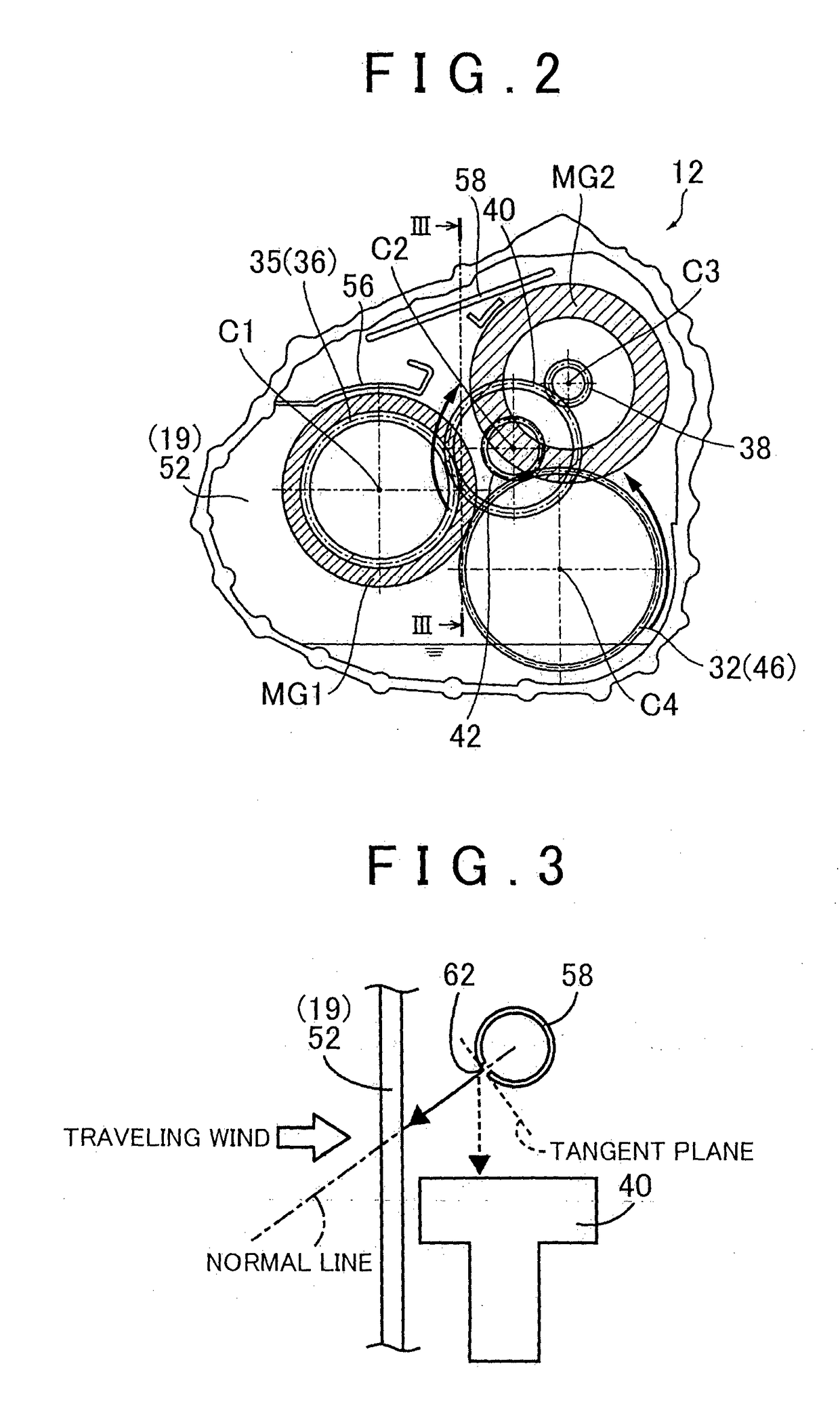
[0019]Here, the normal direction of the hole preferably corresponds to a perpendicular direction to a tangent plane contacting the hole or a direction along a radial line that extends in a radial direction from the center of the pipe and passes the center of the hole.

[0020]A detailed description will hereinafter be made on examples of the present invention with reference to the drawings. Noted that the drawings are appropriately simplified or deformed for the following examples, and thus a dimensional ratio, a shape, and the like of each component is not necessarily depicted to be accurate.

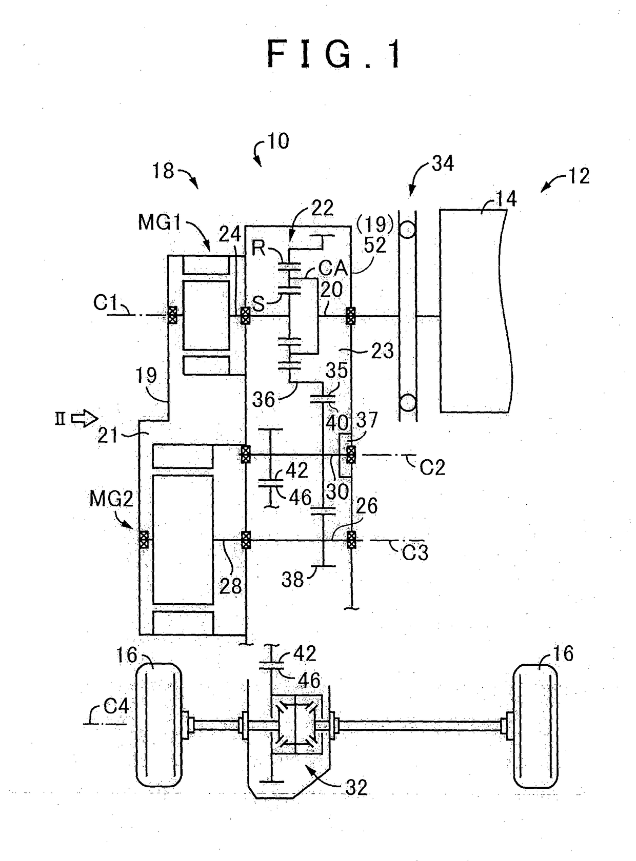
[0021]FIG. 1 is a skeletal view for illustrating a structure of a vehicle drive apparatus 12 (hereinafter, a drive apparatus 12) that is provided in a hybrid vehicle 10 of this example. The vehicle drive apparatus 12 includes: an engine 14 such as a known gasoline engine or a known diesel engine that functions as a traveling drive power source (a power source); and a vehicle power transmission 18 ...


PUM


Abstract

An apparatus includes a case, a motor, a gear mechanism, a lubrication mechanism, and a cooling mechanism. The motor and the gear mechanism are housed in the case. The gear mechanism includes a specified gear and a first gear. A vertical lower section of the first gear is positioned above a surface of the oil. The lubrication mechanism lubricates the gear mechanism by the oil thrown up by the specified gear. The cooling mechanism includes an oil pump and a pipe. The oil pump and the pipe supply the oil reserved in the case to the motor. The pipe is located above the first gear. The pipe has a hole, and the oil discharged from the hole. The hole is positioned above the first gear. A normal line direction of the hole differs from a vertically downward direction. The first gear does not overlap the normal line direction.

Description

BACKGROUND OF THE INVENTION[0001]1. Field of the Invention[0002]The present invention relates to a vehicle drive apparatus including an electric motor.[0003]2. Description of Related Art[0004]In a vehicle drive apparatus that includes an electric motor, a system for supplying oil that is thrown up by a specified gear in the drive apparatus to a gear and a bearing and for supplying the pumped-up oil by an oil pump to the an electric motor has been adopted for a mechanism that lubricates the gear and the bearing and cools the electric motor, the oil pump being disposed along with the gear. There is a case where an oil amount supplied to the gear and the bearing is changed by an oil temperature, and thus it may be difficult to constantly and sufficiently secure a required oil amount. For example, when the oil temperature is low, viscosity of the oil is high. Thus, the oil amount that is supplied to the bearing for a purpose of lubrication may be reduced. On the other hand, when the oil...

Claims


Application Information

Patent Timeline
Patent Type & Authority Applications(United States)
IPC IPC(8): F16H57/04B60K6/445B60K6/365B60K6/405B60K11/02B60L50/16
CPCF16H57/0476B60K6/405B60K11/02B60K6/365B60K6/445B60Y2400/73F16H57/0423B60Y2200/92B60Y2306/03B60Y2306/05Y10S903/902F16H57/0457B60K11/00B60R17/00F16H57/0413F16H57/042B60K6/40F16H57/0409F16H57/0494
Inventor SUENAGA, SHINICHIROHASEGAWA, RYUICHIWATANABE, MASATOOBATA, TATSUOMIYANAGA, SATOSHI
Owner TOYOTA JIDOSHA KK
Why Eureka
Try Eureka