

Laser Welding Assembly And Method
- Summary
- Abstract
- Description
- Claims
- Application Information
AI Technical Summary
Benefits of technology
Problems solved by technology
Method used
Image

Examples
first embodiment
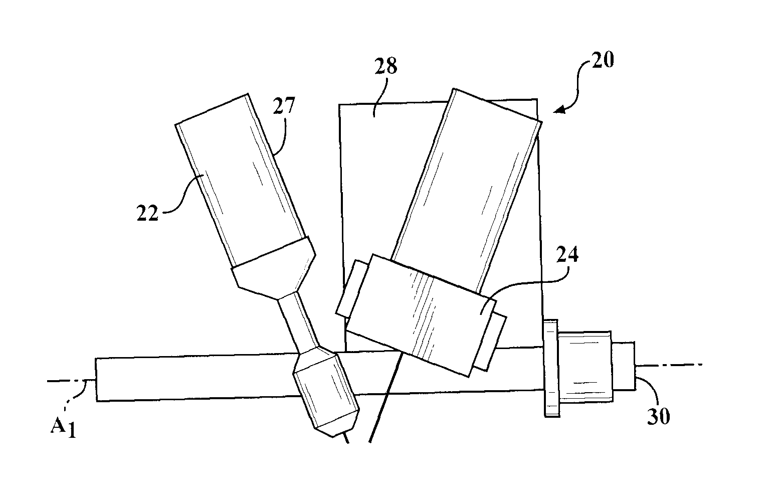
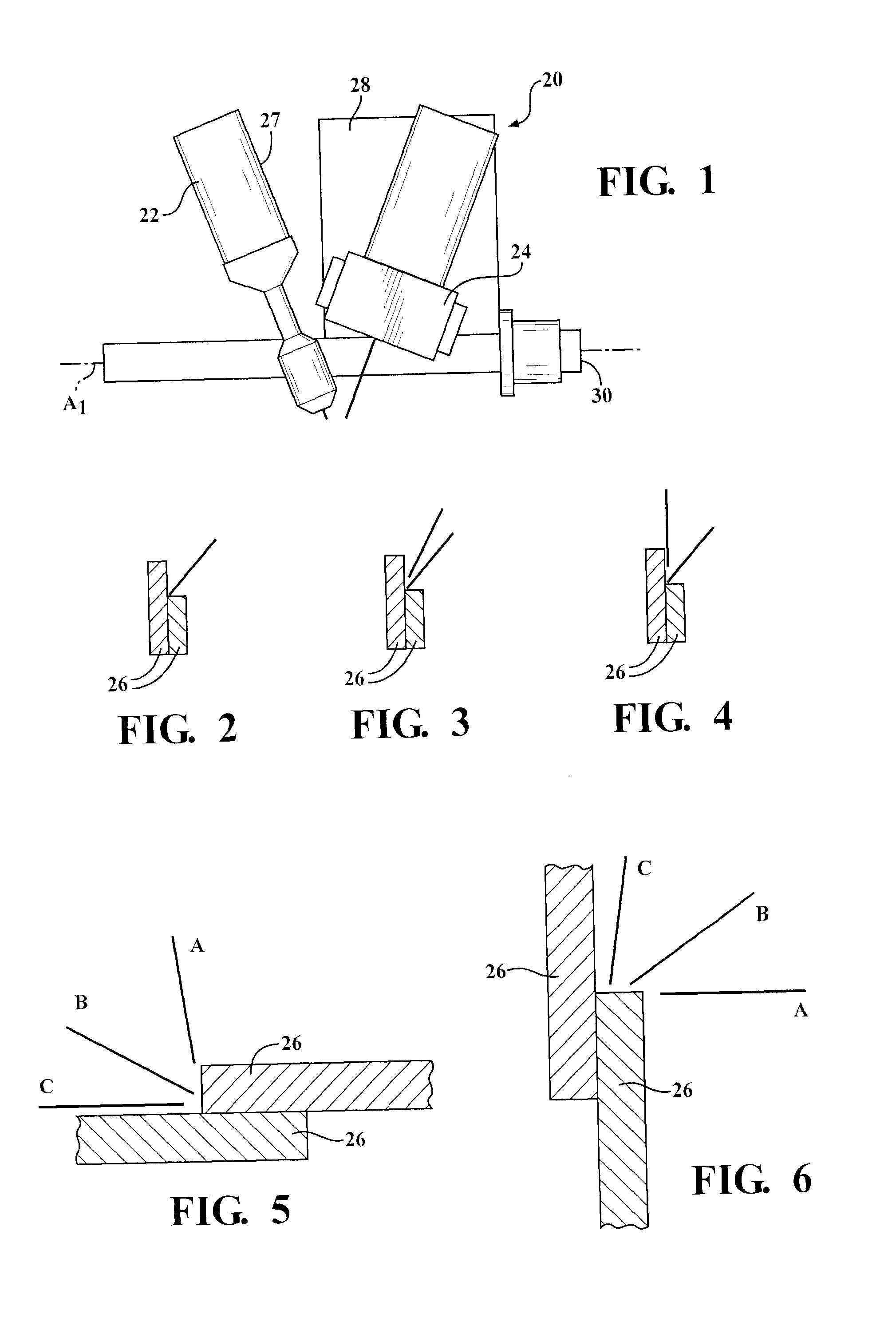
[0039]In the HLAW assembly 20, as shown in FIG. 1, the torch 22 is mounted directly on the robot 27 (also shown in FIG. 8), and the laser head 24 is mounted on a table 28, which is attached to the robot 27. The torch 22 and laser head 24 are angled toward one another such that they are aimed at a point on the joint to be welded adjacent to one another. The torch 22 and laser head 24 are preferably angled relative to one another such that they are aimed at targets adjacent one another such that the melted material produced by the torch 22 overlaps with the melted material produced by the laser head 24 to produce a hybrid laser arc weld between the plates 26. Most preferably, the torch 22 and laser head 24 are aimed at targets with approximately a two millimeter (2 mm) pitch, or gap, between one another. This pitch may be beneficial since it allows both the torch 22 and laser head 24 to pass an area of the joint without the metal cooling therebetween. Alternately, the pitch between th...
second embodiment
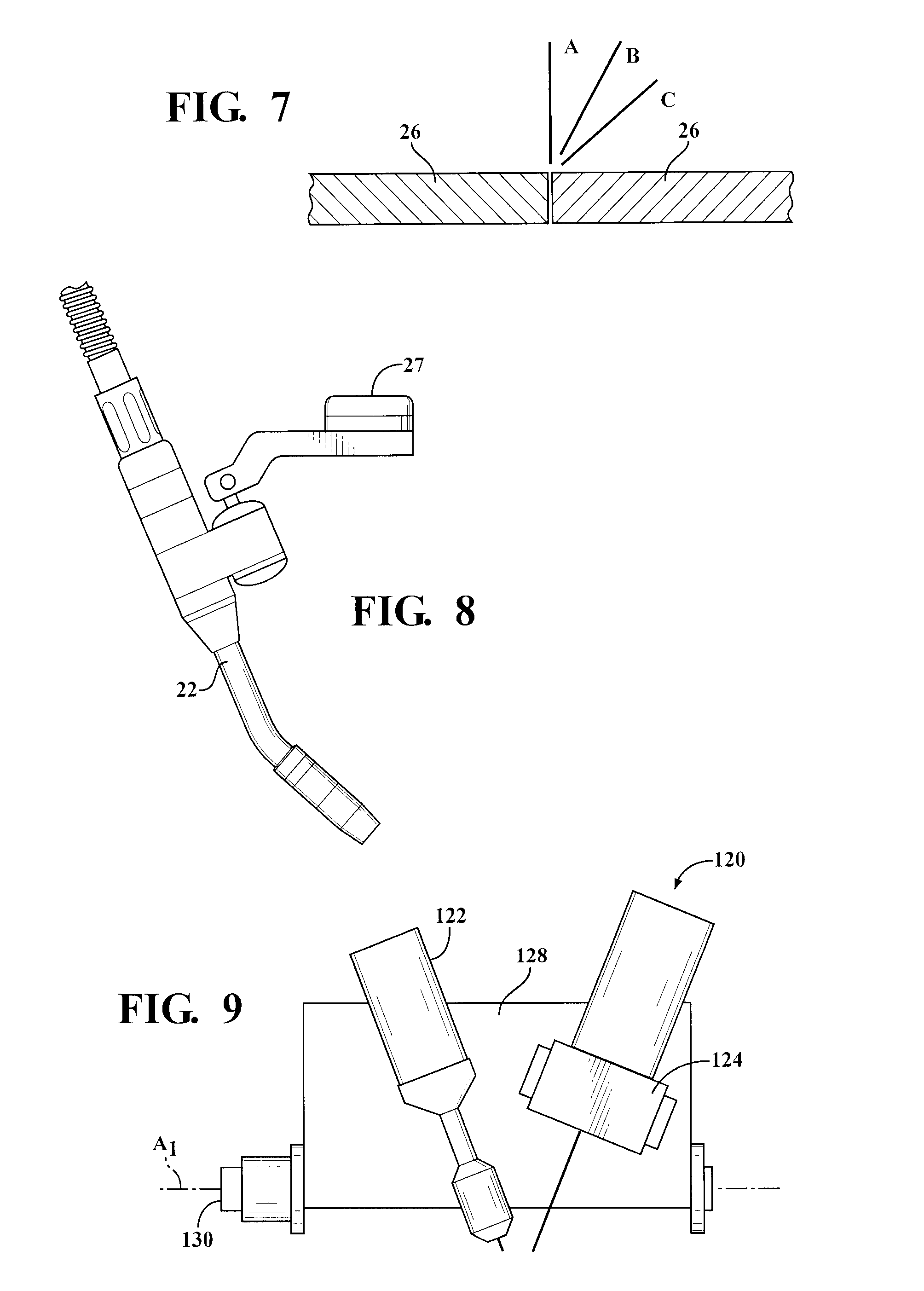
[0044]A second exemplary embodiment of the HLAW assembly 120 is generally shown in FIGS. 9 and 10. In this exemplary embodiment, the torch 122 and laser head 124 are mounted on a common table 128. This arrangement allows the torch 122 and the laser beam to maintain a substantially constant pitch and orientation with respect to one another. The table 128 of the second exemplary embodiment is rotatably coupled to the robot 127 about a first axis A1, and a first servo motor 130 is operatively connected to the table 128 for rotating the table 128. In this configuration, only a single TCP calibration is typically necessary to calibrate both the torch 122 and the laser head 124. The second embodiment is advantageous because it allows the torch 122 and laser head 124 to be quickly and dynamically adjusted together to weld any desirable joint configuration.
third embodiment
[0045]Referring now to FIG. 11, a third exemplary embodiment of the HLAW assembly 220 is generally shown. In this embodiment, the torch 222 and laser head 224 are mounted on separate tables 228, each independently rotatable about the first axis A1. A first servo motor 230 is operatively coupled to the table 228 supporting the torch 222 for rotating the torch 222, and a second servo motor 230 is operatively coupled to the table 228 supporting the laser head 224 for rotating the laser head 224. A TCP calibration may be performed for each movement of either table 228 in order to calibrate the torch 222 and laser head 224 separately. The third embodiment is advantageous because it allows the torch 222 and laser head 224 to be dynamically adjusted independently of one another to optimize the weld for any desirable joint configuration.
[0046]FIGS. 12-24 show additional features of the second exemplary embodiment, though these features are also applicable to the first and third exemplary em...
PUM
| Property | Measurement | Unit |
|---|---|---|
| Length | aaaaa | aaaaa |
Abstract
Description
Claims
Application Information