
Energy efficient network communication device and method

a network communication and energy-saving technology, applied in the field of network communication devices and network communication methods, can solve the problems of many circuit complication and power consumption problems, and the power consumption of traditional network devices is merely a bit less than that in a normal state, so as to achieve energy-saving and reduce power consumption

Active Publication Date: 2014-05-08
REALTEK SEMICON CORP
View PDF7 Cites 16 Cited by
  • Summary
  • Abstract
  • Description
  • Claims
  • Application Information

AI Technical Summary

Benefits of technology

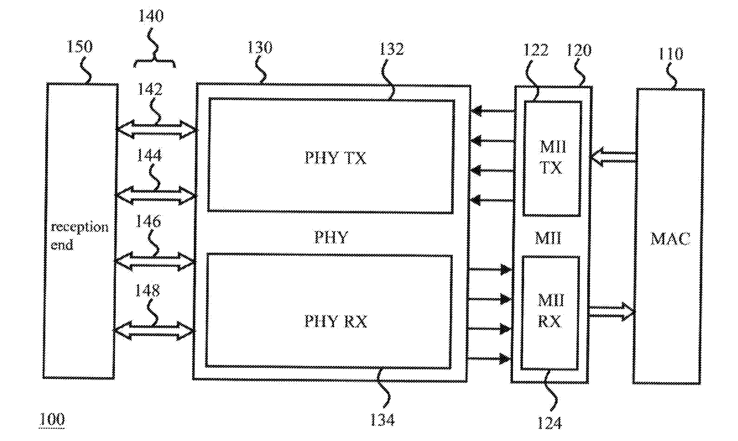
The present invention is about a way to communicate between devices over a network while conserving energy. It involves a method where devices enter an "idle mode" when not actively transmitting or receiving data. They then send a signal to the receiving device to enter a lower power idle mode. The devices use only one or a few pairs of transmission lines to send the signal, and another set of lines to receive the signal. This setup reduces power consumption compared to the normal mode of communication. The devices can then enter a LPI mode to further reduce power consumption, and this mode also results in lower power consumption than the idle mode. Overall, this invention provides a way to conserve energy while still getting the necessary data transfer done between devices on the network.

Problems solved by technology

Unfortunately, although the idle state is applied, the power consumption of the traditional network device is merely a bit less than that in a normal state.
This framework has a data transmission rate higher than that of a traditional device conforming to 1000 BASE-X standard, but it also brings much circuit complication and power consumption issues; moreover, this framework can not support EEE standard, which means that it can not enter the LPI mode to cut the operation of the physical layer circuit for power saving.

Method used


Image

  • Energy efficient network communication device and method
  • Energy efficient network communication device and method
  • Energy efficient network communication device and method

Examples


Embodiment Construction

[0019]The following description uses language by referring to terms of the filed of this invention. If any term is defined in the specification, such term should be explained accordingly. Besides, the connection between objects or events in the disclosed embodiments can be direct or indirect provided that these embodiments are still applicable under such connection. The mentioned “indirect” means that an intermediate object or a physical space is existed between the objects, or an intermediate event or a time interval is existed between the events. In addition, the following description relates to network communication, and thus the known detail in this filed will be omitted if such detail has little to do with the features of the present invention. Furthermore, the shape, size, and ratio of any element and the step sequence of any flow chart in the disclosed figures are just exemplary for understanding, not for limiting the scope of this invention.

[0020]Besides, each embodiment in ...


PUM


Abstract

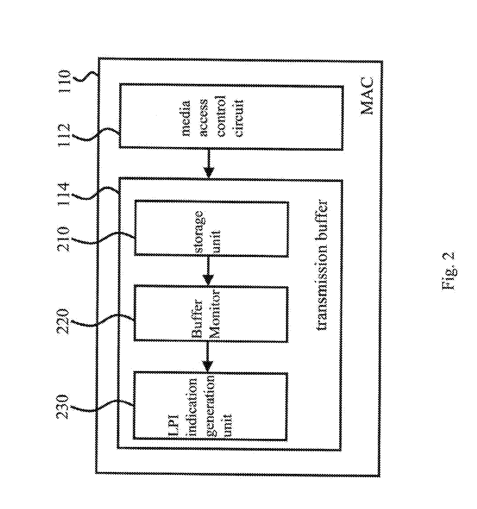
The present invention discloses an energy efficient network communication device comprising: a media-access-controller for outputting a transmission-end low power idle (LPI) indication and receiving a reception-end LPI indication; a media-independent-interface for generating a transmission-end LPI signal according to the transmission-end LPI indication, and generating the reception-end LPI indication according to a reception-end LPI signal; and a physical-layer-circuit, coupled to several pairs of transmission lines, for converting the transmission-end LPI signal into a transmission signal to send it to a reception end for requesting an LPI mode and receiving a reception signal from the reception end to convert it into the reception-end LPI signal. Said physical-layer-circuit uses some of the several pairs of transmission lines for transmission and reception when keeping the other pairs of transmission lines unused to save power; furthermore, the physical-layer-circuit can enter the LPI mode from an idle mode for additional power saving.

Description

BACKGROUND OF THE INVENTION[0001]1. Field of the Invention[0002]The present invention relates to a network communication device and a network communication method, especially to a network communication device and a network communication method capable of power saving.[0003]2. Description of Related Art[0004]In the prior art, after a network connection is established, a traditional network device (e.g. an Ethernet network device in compliance with 1000BASE-T standard) has to send an idle pattern to a reception end continually to thereby keep the connection alive even if the network device is in an idle state with no need to do transmission or reception. Unfortunately, although the idle state is applied, the power consumption of the traditional network device is merely a bit less than that in a normal state. Therefore, in order to save more power, IEEE works out Energy Efficient Ethernet (EEE) standard which allows a network device to enter a low power idle (LPI) mode from the aforeme...

Claims


Application Information

Patent Timeline
Patent Type & Authority Applications(United States)
IPC IPC(8): H04W52/02
CPCH04W52/0203H04L12/12G06F1/3209G06F1/3278G06F1/3287H04L63/0428H04L63/0485H04L63/162Y02D10/00Y02D30/70Y04S40/20
Inventor TSENG, TA-CHINKUO, SHIEH-HSINGHUANG, LIANG-WEILAO, HENG CHEONG
Owner REALTEK SEMICON CORP
Learn More