Analyte sensors having a signal-to-noise ratio substantially unaffected by non-constant noise
- Summary
- Abstract
- Description
- Claims
- Application Information
AI Technical Summary
Benefits of technology
Problems solved by technology
Method used
Image
Examples
example 1
Resistance Domain Configurations to Increased the Analyte Signal Reduce Non-Constant Noise
[0412]Transcutaneous sensors, with electrode, interference, enzyme and resistance (polyurethane blend) domains, were built and tested in non-diabetic hosts. The control and test sensors were built as described in U.S. Publication No. 2006-0020187, which is incorporated herein by reference in its entirety, with the following exception: the resistance domain of the test sensors was formed of 3 layers of a 60% ChronoThane® H (CardioTech International, Wilmington, Mass., USA; the PEO concentration of ChronoThane® H is about 25%) polyurethane blend solution, as compared to a single layer of a 45% ChronoThane® H polyurethane blend solution in the control sensors. Test and control sensors were implanted bilaterally in the abdomens of non-diabetic host volunteers, for a period of about 7 days.
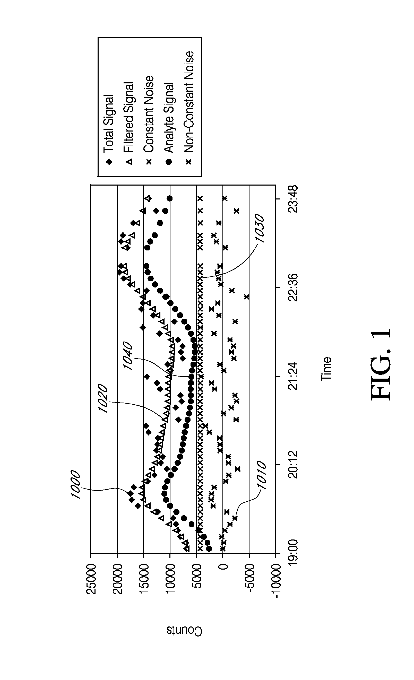
[0413]FIG. 8 illustrates exemplary test results from one test sensor, over a period of about 7 days, after sens...
example 2
A Lubricious Coating Configured to Reduce Non-Constant Noise
[0416]Control and test sensors, with electrode, enzyme and resistance domains, were built as described in U.S. Patent Publication No. US-2006-0020187-A1, including a resistance domain formed using a polyurethane polymer blend having about 8 wt. % PEO, as described in the section entitled “Polyurethane Polymer Material” above. A lubricious coating was applied to the test sensors by dipping them one time into a solution of HydroMed™ (CardioTech International, Inc., Wilmington, Mass., USA) and drying. The control and test sensors were tested in vitro (see Table 1, below). The test sensors (with the lubricious coating) had a substantially increased sensitivity (m) but with no corresponding increase in constant noise (b), when compared to control sensors (no lubricious coating). Accordingly, it was shown that application of a lubricious coating over a polyurethane blend resistance domain of a glucose sensor can (in vitro) substa...
example 3
Discontinuous Hydrophilic Overcoat on Resistance Domain Configured to Reduce Non-Constant Noise
[0418]To determine if a hydrophilic overcoat on the resistance layer can increase the analyte signal component and / or reduce the non-constant noise component, test and control sensors were build and tested in volunteer human hosts, over a period of 3 days. Both the test and control sensors included an electrode layer, an enzyme layer and a polyurethane blend resistance domain. The polyurethane blend used to form the resistance domain included 8% hydrophile (i.e., PEO). After fabrication, the test sensors were sprayed (one time) in a solution of 5% ChronoThane® H (about 25% PEO; CardioTech International, Wilmington, Mass., USA) and cured. Test and control sensors were implanted bilaterally in the abdomens of the volunteer human hosts. FIG. 10 is a graph showing test results from one exemplary sensor. Components of the Total Signal 1000 were determined, as described in Example 1. The Y-axis ...
PUM
 Abstract
Description
Claims
Application Information
 - R&D
- Intellectual Property
- Life Sciences
- Materials
- Tech Scout
- Unparalleled Data Quality
- Higher Quality Content
- 60% Fewer Hallucinations
Browse by: Latest US Patents, China's latest patents, Technical Efficacy Thesaurus, Application Domain, Technology Topic, Popular Technical Reports.
© 2025 PatSnap. All rights reserved.Legal|Privacy policy|Modern Slavery Act Transparency Statement|Sitemap|About US| Contact US: help@patsnap.com


