Hydraulic drive system

a technology of hydraulic pump and drive shaft, which is applied in the direction of fluid coupling, servomotor, coupling, etc., can solve the problems of difficult to control the tilt angle of the hydraulic pump in very small angle units, difficult to achieve a stable discharge flow rate, and difficult to control the discharge flow rate in a precise manner. achieve the effect of controlling with more accuracy, small energy loss, and controlling with more accuracy

Inactive Publication Date: 2014-05-15
KOMATSU LTD
View PDF5 Cites 39 Cited by
  • Summary
  • Abstract
  • Description
  • Claims
  • Application Information

AI Technical Summary

Benefits of technology

[0028]When the target flow rate is within a prescribed range, the control device in the hydraulic drive system according to the first aspect of the present invention uses the flow rate control valve to control the flow rate of the hydraulic fluid being supplied to the hydraulic cylinder. Therefore, when the target flow rate is a very small flow rate, the flow rate of the hydraulic fluid supplied to the hydraulic cylinder is controlled by the flow rate control valve. As a result, the flow rate of the hydraulic fluid being supplied to the hydraulic cylinder is able to be controlled by the flow rate control valve as a very small flow rate even if the minimum controllable flow rate of the discharge flow rate from the hydraulic pump controlled by the pump-flow-rate control unit is not small enough to allow control as a very small flow rate. Consequently, micro-speed control of the hydraulic cylinder is possible.
[0045]The discharge flow rate of the hydraulic pump is controlled as a flow rate equal to or above the target flow rate by controlling the rotation speed of the hydraulic pump when the target flow rate is within the prescribed range in the hydraulic drive system according to the sixteenth aspect of the present invention. As a result, the flow rate of the hydraulic fluid supplied to the hydraulic cylinder can be adjusted by the flow rate control valve and the flow rate of the hydraulic fluid to the hydraulic cylinder can be controlled with more accuracy. Moreover, while hydraulic fluid having a flow rate greater than the flow rate necessary for the hydraulic cylinder is discharged from the hydraulic pump, energy loss is small since the flow rate discharged from the hydraulic pump is originally small when the target flow rate is within the prescribed range.

Problems solved by technology

However, there is a limit to the minimum controllable flow rate of the discharge flow rate of the hydraulic pump and thus it is difficult to control the discharge flow rate of the hydraulic pump in a precise manner as described above.
However, it is difficult to achieve a stable discharge flow rate in the region of a very small tilt angle since the impact of variations in hydraulic fluid leakage from the sliding portion of the hydraulic pump becomes greater.
Moreover, since a friction force acts on the mechanism for varying the tilt angle of the hydraulic pump, it is difficult to control the tilt angle of the hydraulic pump in very small angle units.
However, it is difficult to achieve a stable discharge flow rate in the region of a very small rotation speed since the impact of variations in hydraulic fluid leakage from the sliding portion of the hydraulic pump becomes greater.
Moreover, while hydraulic fluid having a flow rate greater than the flow rate necessary for the hydraulic cylinder is discharged from the hydraulic pump, energy loss is small since the flow rate discharged from the hydraulic pump is originally small when the target flow rate is within the prescribed range.

Method used


Image

  • Hydraulic drive system
  • Hydraulic drive system
  • Hydraulic drive system

Examples


first embodiment

1. First Embodiment

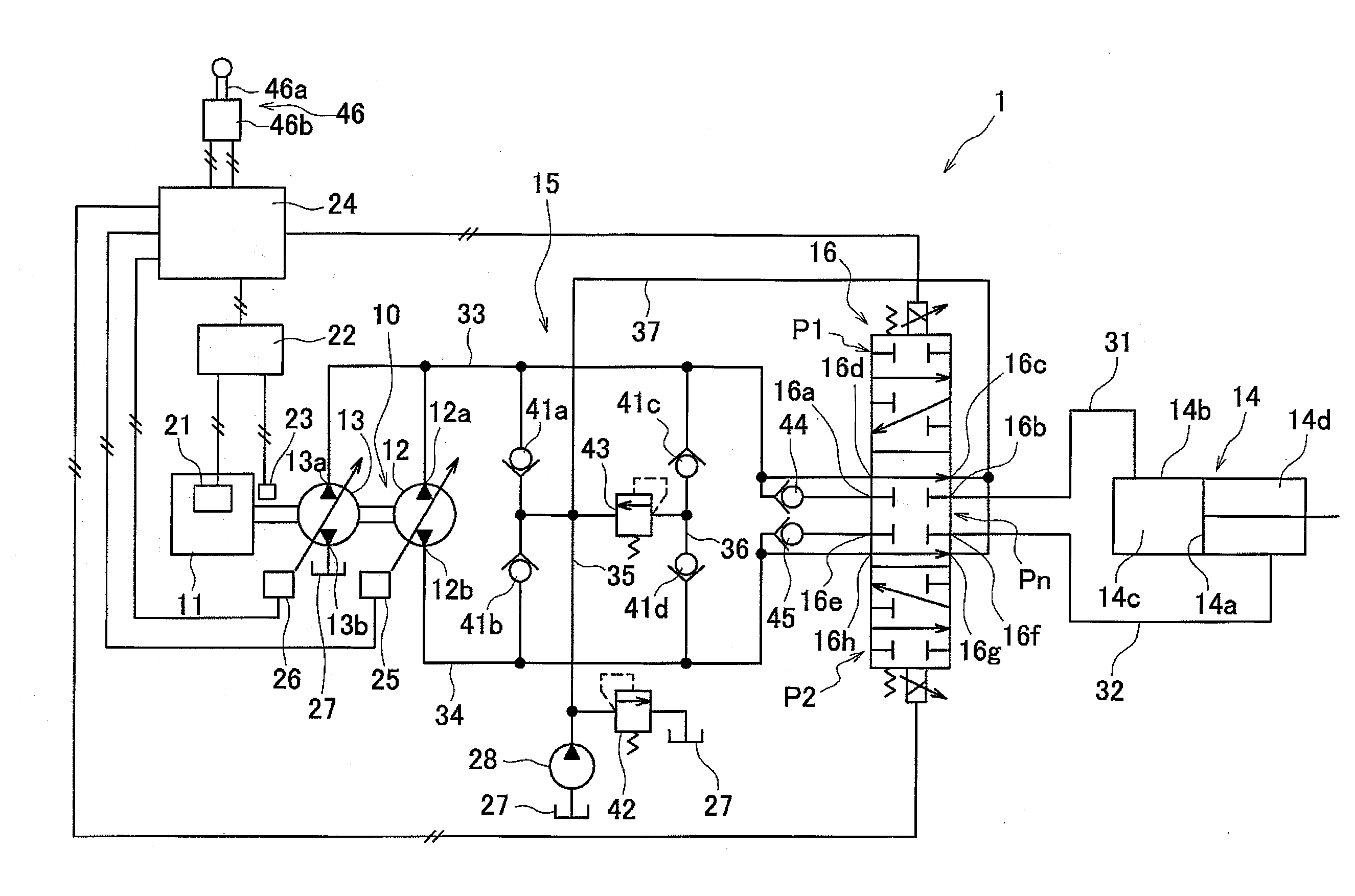
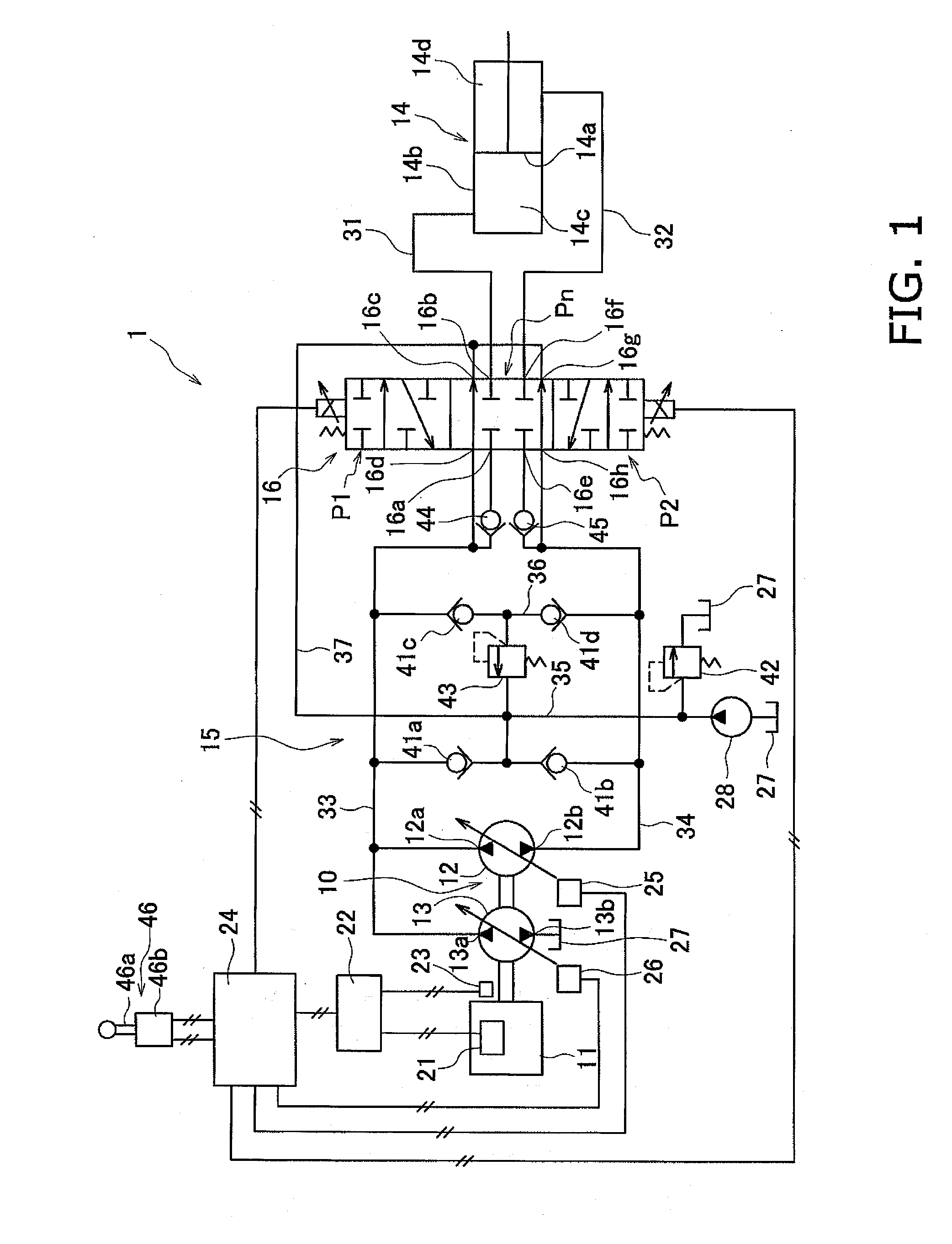
[0061]FIG. 1 is a block diagram of a configuration of a hydraulic drive system 1 according to a first embodiment of the present invention. The hydraulic drive system 1 is installed on a work machine such as a hydraulic excavator, a wheel loader, or a bulldozer. The hydraulic drive system 1 includes an engine 11, a main pump 10, a hydraulic cylinder 14, a hydraulic fluid path 15, a flow rate control valve 16, and a pump controller 24.

[0062]The engine 11 drives a first hydraulic pump 12 and a second hydraulic pump 13. The engine 11 is an example of a driving source in the present invention. The engine 11 is a diesel engine, for example, and the output of the engine 11 is controlled by adjusting an injection amount of fuel from a fuel injection device 21. The adjustment of the fuel injection amount is performed by the engine controller 22 controlling the fuel injection device 21. An actual rotation speed of the engine 11 is detected by a rotation speed sensor 23, and...

second embodiment

2. Second Embodiment

[0096]Next, a hydraulic drive system 2 according to the second embodiment of the present invention will be described. FIG. 3 is a block diagram of a configuration of a hydraulic drive system 2 according to the second embodiment. Configurations in FIG. 3 that are the same as the first embodiment are given the same reference numbers as in the first embodiment.

[0097]The hydraulic fluid path 15 in the hydraulic drive system 2 includes a first adjustment path 51 and a second adjustment path 52 in place of the adjustment path 37 in the first embodiment. The first adjustment path 51 and the second adjustment path 52 are each connected to the hydraulic fluid tank 27. The hydraulic drive system 2 further includes a first unloading valve 53 and a second unloading valve 54. The first adjustment path 51 is connected to the first pump path 33 via the first unloading valve 53. The second adjustment path 52 is connected to the second pump path 34 via the second unloading valve ...

third embodiment

3. Third Embodiment

[0116]Next, a hydraulic drive system 3 according to the third embodiment of the present invention will be described. FIG. 5 is a block diagram of a configuration of a hydraulic drive system 3 according to the third embodiment. Configurations in FIG. 5 that are the same as the first embodiment are given the same reference numbers as in the first embodiment. Configurations in FIG. 5 that are the same as the second embodiment are given the same reference numbers as in the second embodiment.

[0117]As illustrated in FIG. 5, the flow rate control valve 16 is switchable between a third position state P3 and a fourth position state P4 in addition to the first position state P1, the second position state P2, and the neutral position state Pn of the second embodiment.

[0118]The flow rate control valve 16 allows communication between the first pump port 16a and the first cylinder port 16b and between the first bypass port 16d and the first adjustment port 16c in the third posi...


PUM


Abstract

A hydraulic driving system includes a hydraulic pump, a driving source, a hydraulic cylinder, a closed circuit hydraulic path between the pump and cylinder, a pump-flow-rate control unit controlling a discharge flow rate of the pump, a flow rate control valve between the pump and the cylinder in the fluid path, a directional control unit, a target flow rate setting unit and a control device. The directional control unit allows a flow of fluid from the pump to the cylinder and prohibits a flow of fluid from the cylinder to the pump when fluid is supplied from the pump to the cylinder via the flow rate control valve. The control device controls fluid flow to the cylinder with the flow rate control valve when the target flow rate is within a prescribed range, and with the pump-flow-rate control unit when the target flow rate is greater than the prescribed range.

Description

CROSS-REFERENCE TO RELATED APPLICATIONS[0001]This application is a U.S. National stage application of International Application No. PCT / JP2012 / 070603, filed on Aug. 13, 2012. This U.S. National stage application claims priority under 35 U.S.C. §119(a) to Japanese Patent Application No. 2011-182938, filed in Japan on Aug. 24, 2011, the entire contents of which are hereby incorporated herein by reference.BACKGROUND[0002]1. Field of the Invention[0003]The present invention relates to a hydraulic drive system.[0004]2. Background Information[0005]Work machines such as a hydraulic excavator or a wheel loader are equipped with working instrument driven by a hydraulic cylinder. Hydraulic fluid discharged from a hydraulic pump is supplied to the hydraulic cylinder. The hydraulic fluid is supplied via a hydraulic circuit to the hydraulic cylinder. For example, Japan Patent Laid-open Patent Publication JP-A-2009-511831 describes a work machine equipped with a hydraulic closed circuit for suppl...

Claims


Application Information

Patent Timeline
Patent Type & Authority Applications(United States)
IPC IPC(8): F15B11/042E02F9/22F15B11/04
CPCF15B2211/6346F15B2211/20561F15B2211/27F15B2211/633F15B2211/613E02F9/2232E02F9/2296F15B2211/785E02F9/2285F15B2211/7053E02F9/2217F15B2211/20546E02F9/2292F15B2211/20576E02F9/2289E02F9/2228F15B11/0423F15B11/0413
Inventor AKIYAMA, TERUOIIDA, NOBORUSAITO, KOJIWATANABE, TAKAYUKIYAMASHITA, KOJI
Owner KOMATSU LTD
Why Eureka
Try Eureka