Mass Spectrometer

a mass spectrometer and mass spectrometer technology, applied in the field of mass spectrometers, can solve the problems of reducing the overall transmission efficiency of ions, fragment or product ions produced within the fragmentation cell may also become lost due to scattering effects, and the yield of product or fragment ions to exit, so as to maximise the yield of product or fragment ions.

Active Publication Date: 2014-05-15
MICROMASS UK LTD
View PDF1 Cites 4 Cited by
  • Summary
  • Abstract
  • Description
  • Claims
  • Application Information

AI Technical Summary

Benefits of technology

[0162]It is generally the case that the kinetic energy of product or fragment ions when first formed is relatively high e.g. a few electron-volts. However, it is also usually desirable to cool the product or fragment ions (i.e. reduce their kinetic energy and energy spread) before they exit the gas collision cell. This can help to improve the performance of a mass analyser arranged downstream of the gas collision cell and which is used to analyse the product or fragment ions which emerge from the gas collision cell. Therefore, the experimental conditions are usually arranged such that the product or fragment ions are formed some distance before the exit of the gas collision cell so that they may be collisionally cooled prior to exiting the gas collision cell. Ideally the product ions are thermalised (i.e. their kinetic energies are reduced to that of the bath gas) by the time they exit the gas collision cell.
[0169]The various embodiments enable the position along the length of the gas collision cell at which the RF voltage changes from one to another to be optimised such as to maximise the yield of product or fragment ions exiting the gas collision cell.
[0170]This approach may be extended such that according to another embodiment three or more different AC or RF voltages may be applied to groups of electrodes along the length of the gas collision cell. The positions along the length of the gas collision cell at which the three or more AC or RF voltages are changed may be optimised such as to maximise the yield of product or fragment ions exiting the gas collision cell.
[0175]An advantage of using an RF ring stack or ion tunnel ion guide is that the ion guide can relatively easily be divided into a number of separate axial sections. Different AC or RF voltages can therefore be applied to different sections along the length of the gas collision cell.
[0178]In most instances the mass to charge ratio of the product or fragment ion will be less than that of the parent or precursor ion and hence the optimum Rh field at the exit of the gas collision cell will preferably be less than that at the entrance of the gas collision cell. Therefore, in these instances the ions will preferably experience an axial force which preferably propels the ions forwards towards the exit of the gas collision cell as a result of the change in magnitude of the AC or RF electric field along the length of the gas collision cell. In general, this is a further advantage of IC the preferred embodiment since the background gas present in the gas collision cell will normally slow the movement of ions such that the transit time of ions may become excessively long. Advantageously, the pseudo-force resulting from the reduction in RF field strength will accelerate the ions towards the exit of the gas collision cell and hence will help to reduce the transit time of ions through the gas collision cell.
[0181]According to another less preferred embodiment the AC or RF electric field strength may be changed at one or more positions along the length of the gas collision cell by changing the mechanical dimensions of the electrodes to which the AC or RF voltage is applied. For example, in the case of a ring stack ion guide the AC or RF electric field strength may be reduced by increasing the internal diameter of the electrode apertures and / or by increasing the spacing between electrodes for the same applied RF voltage.

Problems solved by technology

However, the energetic collision of parent ions with gas molecules can cause parent ions to become scattered and this can cause parent ions to become lost prior to fragmentation.
Fragment or product ions produced within the fragmentation cell may also become lost due to scattering effects.
However, outside of this range the overall transmission efficiency of ions will be reduced.
As a consequence, ions having relatively low mass to charge ratios will follow trajectories with relatively large radial excursions and ions having mass to charge ratios below a certain critical value may strike the electrodes of the RF ion guide and hence become lost to the system.
As a consequence, ions having relatively high mass to charge ratios and which are scattered are less effectively confined by the RF ion guide and the ion transmission efficiency starts to decrease with increasing mass to charge ratio.
A problem with a conventional gas collision cell is that parent or precursor ions which initially enter the collision cell will have a first relatively high mass to charge ratio whereas the resulting product or fragment ions formed in the gas cell (and which subsequently exit the gas collision cell) will have a second relatively low mass to charge ratio.

Method used


Image

  • Mass Spectrometer
  • Mass Spectrometer
  • Mass Spectrometer

Examples


Embodiment Construction

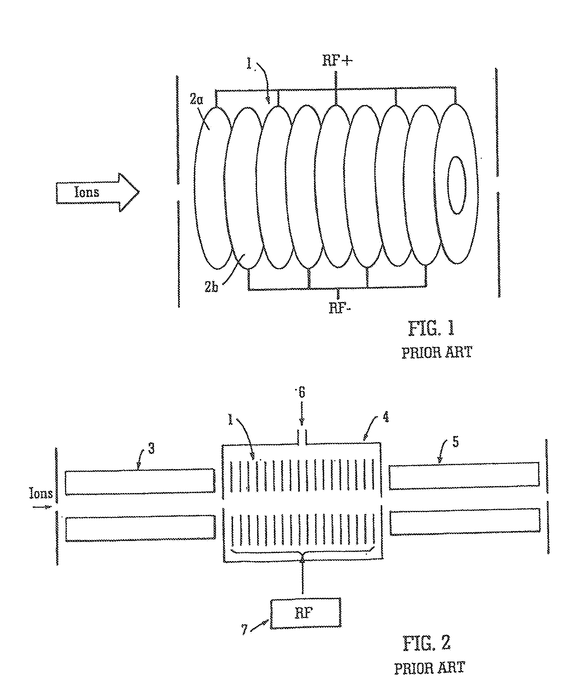
[0194]A preferred embodiment of the present invention will now be described. FIG. 1 shows for illustrative purposes only an RF ion guide comprising a ring or ion tunnel stack assembly 1. The ion guide comprises a stack of ring electrodes 2a,2b. Opposite phases of an AC or RF voltage are applied to axially adjacent electrodes 2a,2b.

[0195]The electrodes are approximately 0.5 mm thick and have an axial centre to centre spacing in the range 1 to 1.5 mm. The inner aperture of the ring electrodes may be in the range 4 mm to 6 mm diameter.

[0196]The frequency of the AC or RF voltage is in the range 300 kHz to 3 MHz and the AC or RF voltage has an amplitude in the range of 500-1000 V peak to peak. The optimum, amplitude of the AC or RF voltage depends upon the exact dimensions of the assembly, the frequency of the AC or RF voltage and the mass to charge ratio of the ions being transmitted.

[0197]FIG. 2 shows a known tandem quadrupole mass spectrometer or triple quadrupole arrangement. The kn...


PUM


Abstract

A collision or fragmentation cell is disclosed comprising a plurality of electrodes wherein a first RF voltage is applied to an upstream group of electrodes and a second different RF voltage is applied to a downstream group of electrodes. The radial confinement of parent ions entering the collision or fragmentation cell is optimised by the first RF voltage applied to the upstream group of electrodes and the radial confinement of daughter or fragment ions produced within the collision or fragmentation cell is optimised by the second different RF voltage applied to the downstream group of electrodes.

Description

CROSS REFERENCE TO RELATED APPLICATIONS[0001]This application is a continuation of U.S. patent application Ser. No. 12 / 445,774 filed Aug. 17, 2010, which is the National Stage of International Application No PCT / GB2007 / 003937, filed Oct. 16, 2007, which claims benefit of and priority to U.S. Provisional Patent Application No. 60 / 866,305, filed on Nov. 17, 2006, United Kingdom Application No. 06020468.9 which was filed on Oct. 16, 2006 and United Kingdom Application No. 0622966.0 which was filed on Nov. 17, 2006. The contents of these applications are expressly incorporated herein by reference in their entirety.BACKGROUND OF THE INVENTION[0002]The present invention relates to a mass spectrometer and a method of mass spectrometry.[0003]A tandem mass spectrometer is known which comprises an ion source, a mass filter which is arranged to transmit parent ions having a particular mass to charge ratio, a fragmentation cell arranged downstream of the mass filter which is arranged to fragmen...

Claims


Application Information

Patent Timeline
Patent Type & Authority Applications(United States)
IPC IPC(8): H01J49/06H01J49/34
CPCH01J49/34H01J49/065H01J49/0045H01J49/4235H01J49/062H01J49/422H01J49/005H01J49/0031H01J49/004
Inventor KENNY, DANIEL JAMESBATEMAN, ROBERT HAROLDGREEN, MARTIN RAYMONDWILDGOOSE, JASON LEEPRINGLE, STEVEN DEREK
Owner MICROMASS UK LTD
Why Eureka
Try Eureka