Flexible organic electroluminescent device and method for fabricating the same

a light-emitting diode and flexible technology, applied in the direction of thermoelectric devices, identification means, instruments, etc., can solve the problems of easy introduction of inability to serve as a barrier, and inability to effectively introduce water into the oled device, etc., to achieve the effect of enhancing reliability

Active Publication Date: 2014-05-15
LG DISPLAY CO LTD
View PDF1 Cites 25 Cited by
  • Summary
  • Abstract
  • Description
  • Claims
  • Application Information

AI Technical Summary

Benefits of technology

[0047]Therefore, an aspect of the detailed description is to provide a flexible organic electroluminescent device capable of enhancing reliability by preventing water from being introduced thereinto, by forming a partition wall pattern to enclose a panel outside the panel, in a separate manner from an organic layer formed in an active area, and a method for fabricating the same.

Problems solved by technology

Firstly, in the related art face seal structure, e. g., in a lamination structure among the passivation layer 39, the adhesive 41 and the barrier film 43, the passivation layer 39 and the barrier film 43 serve as a barrier for preventing introduction of water into the OLED device. However, the adhesive 41 cannot serve well as a barrier. This means that introduction of water occurs easily from the side surfaces of the OLED device, rather than from the upper surface.
Secondly, if foreign materials or cracks do not occur between thin films in the related art face seal structure, introduction of water into the OLED device does not occur. However, as shown in FIG. 4, introduction of water into the OLED device actually occurs due to foreign materials, etc. generated when a lower layer is processed.
This may result in oxidation of a cathode of the OLED device.

Method used


Image

  • Flexible organic electroluminescent device and method for fabricating the same
  • Flexible organic electroluminescent device and method for fabricating the same
  • Flexible organic electroluminescent device and method for fabricating the same

Examples


Embodiment Construction

[0066]Description will now be given in detail of the exemplary embodiments, with reference to the accompanying drawings. For the sake of brief description with reference to the drawings, the same or equivalent components will be provided with the same reference numbers, and description thereof will not be repeated.

[0067]Hereinafter, a flexible organic electroluminescent device (OLED) according to the present invention will be explained in more detail with reference to the attached drawings.

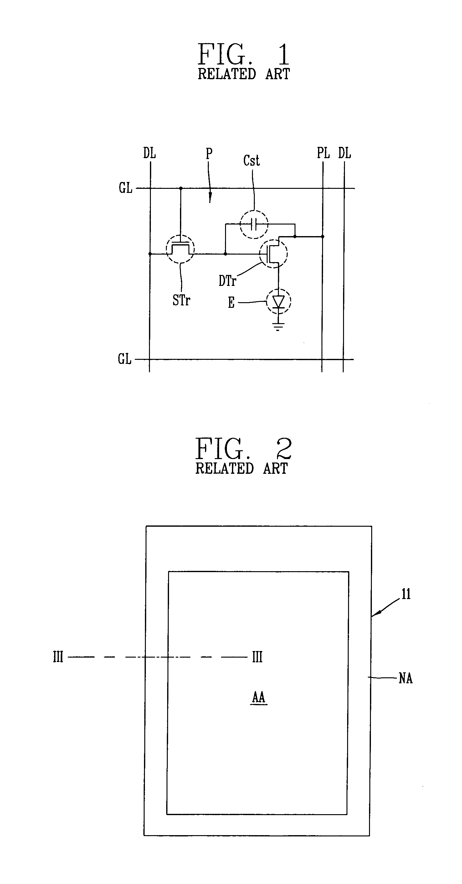
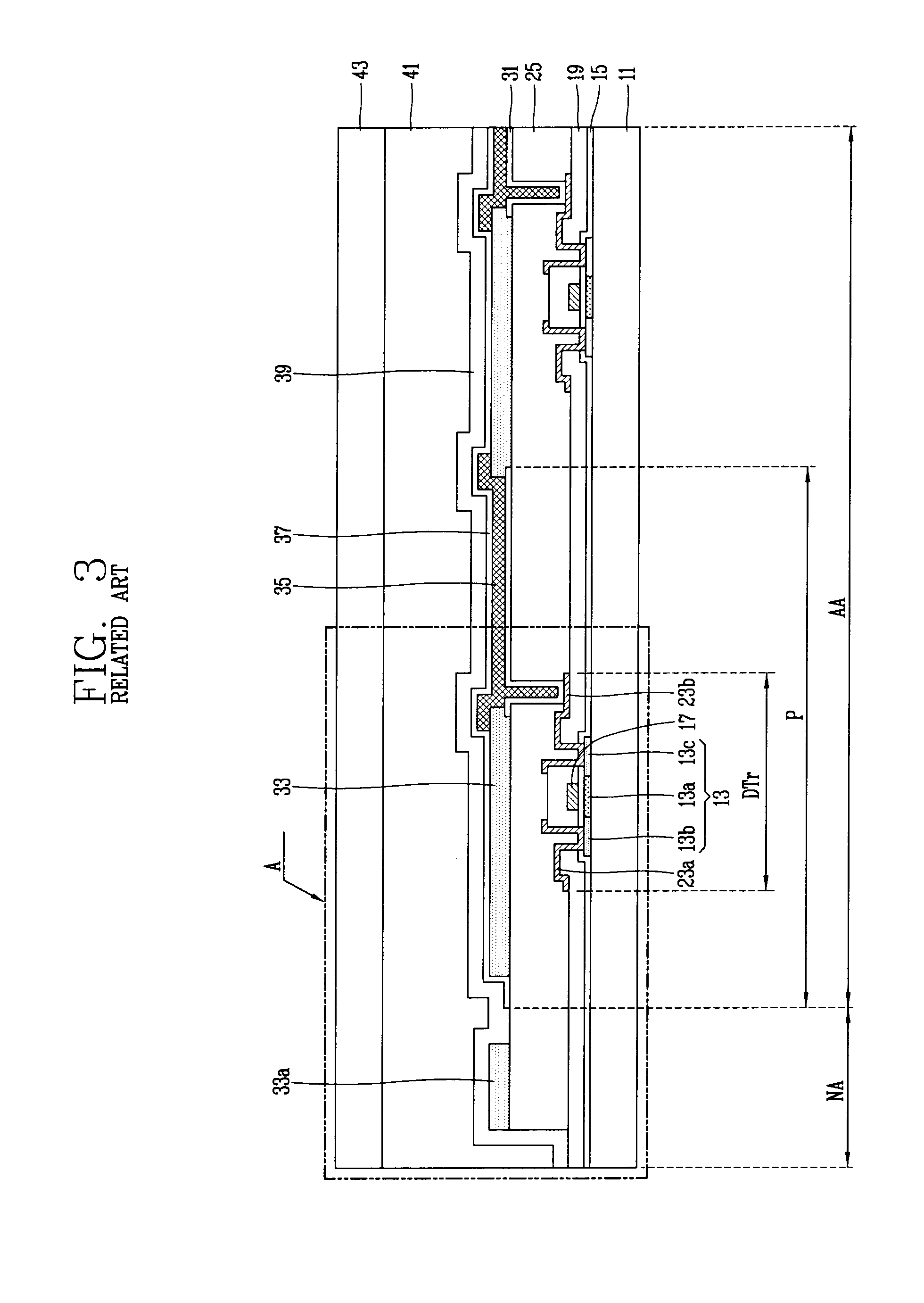
[0068]FIG. 5 is a planar view schematically illustrating a flexible OLED device according to the present invention.

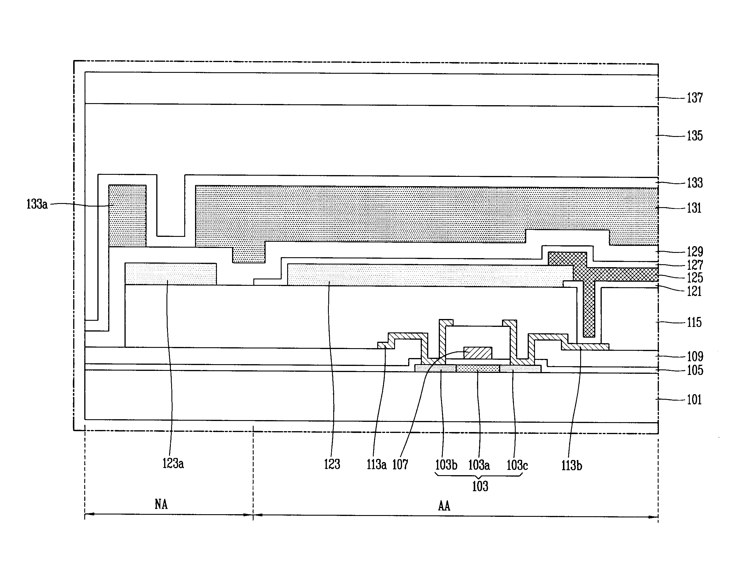
[0069]FIG. 6 is a sectional view taken along line ‘VI-VI’ in FIG. 5, which schematically illustrates a flexible OLED device according to the present invention.

[0070]FIG. 7 is an enlarged sectional view of part ‘B’ in FIG. 6, which schematically illustrates a flexible OLED device where a partition wall pattern is formed in a non-active area so as to enclose an active area.

[0071]The fle...


PUM


Abstract

Disclosed are a flexible organic electroluminescent device, and a method for fabricating the same. The flexible organic electroluminescent device comprises a non-active area formed outside an active area of a substrate; a switching thin film transistor and a driving thin film transistor on the substrate; an interlayer insulating layer formed on the substrate; a first electrode formed on the interlayer insulating layer; a bank formed in the non-active area of the substrate; an organic light-emitting layer formed on the first electrode; a second electrode formed on the organic light-emitting layer; a first passivation layer formed on the substrate; an organic layer formed on the first passivation layer; a partition wall pattern formed on the first passivation layer; a second passivation layer formed on the first passivation layer; and a barrier film disposed to face the substrate.

Description

CROSS REFERENCE TO RELATED APPLICATIONS[0001]Pursuant to 35 U.S.C. §119(a), this application claims the benefit of Korean Patent Application No. 10-2012-0126907, filed on Nov. 9, 2012, the contents of which are incorporated by reference for all purposes herein in its entirety.BACKGROUND OF THE INVENTION[0002]1. Field of the Invention[0003]The present invention relates to an organic light-emitting diode (OLED) device. More particularly, the invention relates to a flexible organic electroluminescent device having an increased lifespan by preventing introduction of water thereto, and a method for fabricating the same.[0004]2. Discussion of the Related Art[0005]An organic light-emitting diode (OLED) device, one type of flat panel display device, has high brightness and a low operation voltage. Further, the OLED device has a high contrast ratio because it is a spontaneous light-emitting type, and it can implement a display of an ultra thin thickness. The OLED device can easily implement ...

Claims


Application Information

Patent Timeline
Patent Type & Authority Applications(United States)
IPC IPC(8): H01L27/32H01L51/56
CPCH01L51/56H01L27/32H10K59/12H10K50/844H10K2102/311Y02E10/549G09F9/301H05B33/04H10K77/111H10K71/00
Inventor KIM, DO HYUNGKIM, MI SOCHOI, CHI MIN
Owner LG DISPLAY CO LTD
Why Eureka
Try Eureka