Supercharge Your Innovation With Domain-Expert AI Agents!

Electrical machine comprising a safety circuit

a safety circuit and electric machine technology, applied in the field of electric machines, can solve the problems of high braking torque generated, safety risk, and inability to steer a vehicl

Inactive Publication Date: 2014-05-15
ROBERT BOSCH GMBH
View PDF10 Cites 4 Cited by
  • Summary
  • Abstract
  • Description
  • Claims
  • Application Information

AI Technical Summary

Benefits of technology

This invention is for an electrical machine that has a field winding with a separate fuse that automatically trips in the event of an overcurrent due to a fault. This prevents a braking torque from occurring in the event of a fault and ensures that the machine can be safely used in safety-critical devices where braking torque must not be exerted by the machine. The field circuit can be connected to a star point which interconnects the winding phases.

Problems solved by technology

In the event of a breakdown of the driver circuit, it is necessary to prevent the electrical machine from building up an electrical braking torque in addition to its mechanical running difficulties owing to the loss of the assistance torque.
Particularly when the field winding is connected between a star point in the electrical machine and a ground potential, a fault may even lead to overexcitation, by means of which a high braking torque would be generated.
When an electrical machine of this kind is used in a steering system, this can lead to an inability to steer a vehicle and therefore constitutes a safety risk.
Measures for disconnecting the star point of the electrical machine in the event of a fault occurring are generally complex since a special switch, for example a star point relay, is required for this purpose.

Method used


Image

  • Electrical machine comprising a safety circuit
  • Electrical machine comprising a safety circuit

Examples


Embodiment Construction

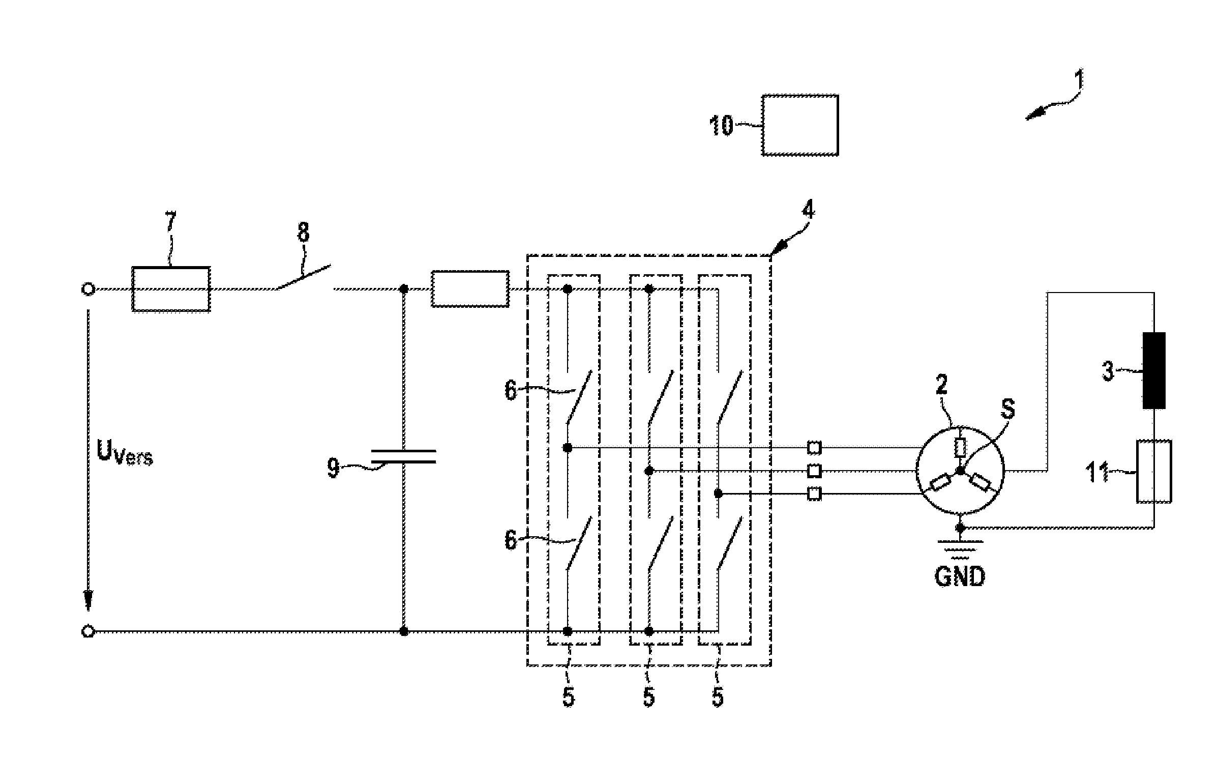
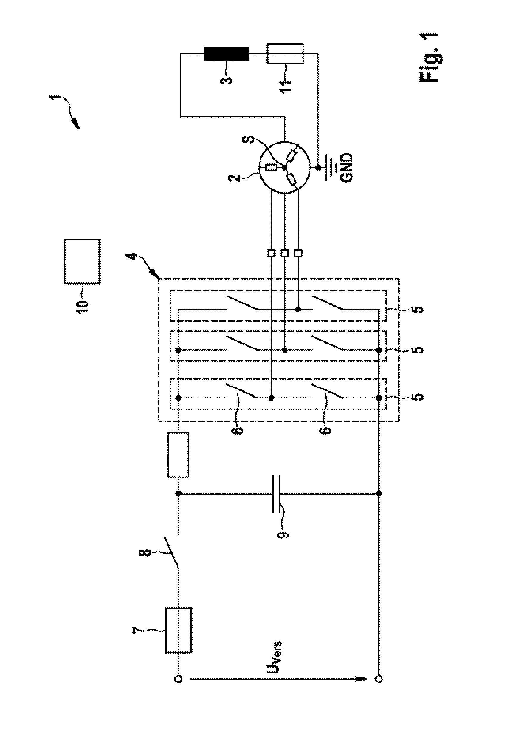
[0031]FIG. 1 shows a motor system 1 comprising an electrical machine 2 which, in the present case, is of three-phase design. The electrical machine 2 has a stator arrangement with three winding phases which are interconnected by means of a star point S to form a star point circuit.

[0032]The rotor (not shown) of the electrical machine 2 is formed from soft-magnetic material and an excitation magnetic field, which has substantially the same function as the permanent magnets in the rotor of a synchronous machine, is applied to said rotor by a field winding 3 which is arranged in a stationary manner. The field winding 3 is usually designed inside the stator, so that the excitation magnetic field enters the rotor and is deflected there, so that a magnetic field which serves to drive the rotor is formed in an air gap between rotor poles of the rotor and the stator.

[0033]In order to supply a current to the circuit which is formed with the field winding 3, the field winding 3 is connected b...


PUM


Abstract

The invention relates to an electrically excited machine (2), in particular for use in a steering system of a motor vehicle, comprising: a stator with a stator winding having multiple phases; an exciter winding (3) which is arranged so as to couple an excitation magnetic field into a rotor that is movably disposed relative to the rotor so that a magnetic field is generated in an air gap between the stator and the rotor; and an exciting circuit having a fuse (11) which is automatically triggered in the event of an overcurrent.

Description

BACKGROUND OF THE INVENTION[0001]The present invention relates to electrical machines, in particular electrically excited electrical machines, such as machines with hybrid excitation or external excitation for example. In particular, the present invention relates to electrically excited electrical machines for use in steering systems and, in particular, measures for reducing a braking torque which occurs in the event of a fault.[0002]Electrical machines with external excitation or hybrid excitation require two further electrical contact-making means for the field winding in comparison to machines with permanent-magnet excitation. The field winding usually has to be actuated by a dedicated actuation unit, a field circuit.[0003]As an alternative, the field winding can also be supplied with current by means of the driver circuit which operates the winding phases of the electrical machine. In this case, the field winding is connected between a star point, by means of which the winding p...

Claims


Application Information

Patent Timeline
IPC IPC(8): H02K11/00
CPCH02K11/0057H02H7/0805H02H7/0833H02K19/12H02K11/27H02H7/06H02H7/08H02K11/00H02P29/02
Inventor RIEGER, VINCENTNEUBURGER, MARTIN
Owner ROBERT BOSCH GMBH
Features
  • R&D
  • Intellectual Property
  • Life Sciences
  • Materials
  • Tech Scout
  • Unparalleled Data Quality
  • Higher Quality Content
  • 60% Fewer Hallucinations
Learn More