
Fixed image display device and method of manufacturing the same

a fixed image display device and organic technology, applied in the direction of optics, instruments, non-linear optics, etc., can solve the problems of high alignment requirements for manufacturing non-uniform switching of known fixed image display devices based on layered electrochemical active and organic materials, and the end user may observe the fixed image of the fixed image display device. , to achieve the effect of shortening the switching time and increasing the voltag

Inactive Publication Date: 2014-05-15
ACREO SWEDISH ICT
View PDF1 Cites 12 Cited by
  • Summary
  • Abstract
  • Description
  • Claims
  • Application Information

AI Technical Summary

Benefits of technology

The present invention provides a fixed image display device that can effectively hide the image when it is not in use. The device has a uniform display area with a pre-determined color scheme and texture. The device is manufacturable using conventional printing techniques like bar coating, screen printing, and ink-jet printing. The invention also allows for easy scalability to larger manufacturing scales which can result in faster and lower production costs.

Problems solved by technology

However, a drawback with known fixed image display devices based on layered electrochemically active and organic materials, is that the fixed image of the fixed image display device may be observed by the end user even before the application of an activation voltage.
In addition, high alignment requirements for manufacturing known fixed image display devices entail expensive and inefficient manufacturing processes involving e.g. exact matching of the opacifier layer in relation to the chromic layer.
Furthermore, known fixed image display devices based on layered electrochemically active and organic material normally suffer from non-uniform switching of the fixed image, as the switch of the electrochromic material normally starts at one end of the material and progresses throughout the remaining electrochromic material until the whole volume is switched.

Method used


Image

  • Fixed image display device and method of manufacturing the same
  • Fixed image display device and method of manufacturing the same
  • Fixed image display device and method of manufacturing the same

Examples


example

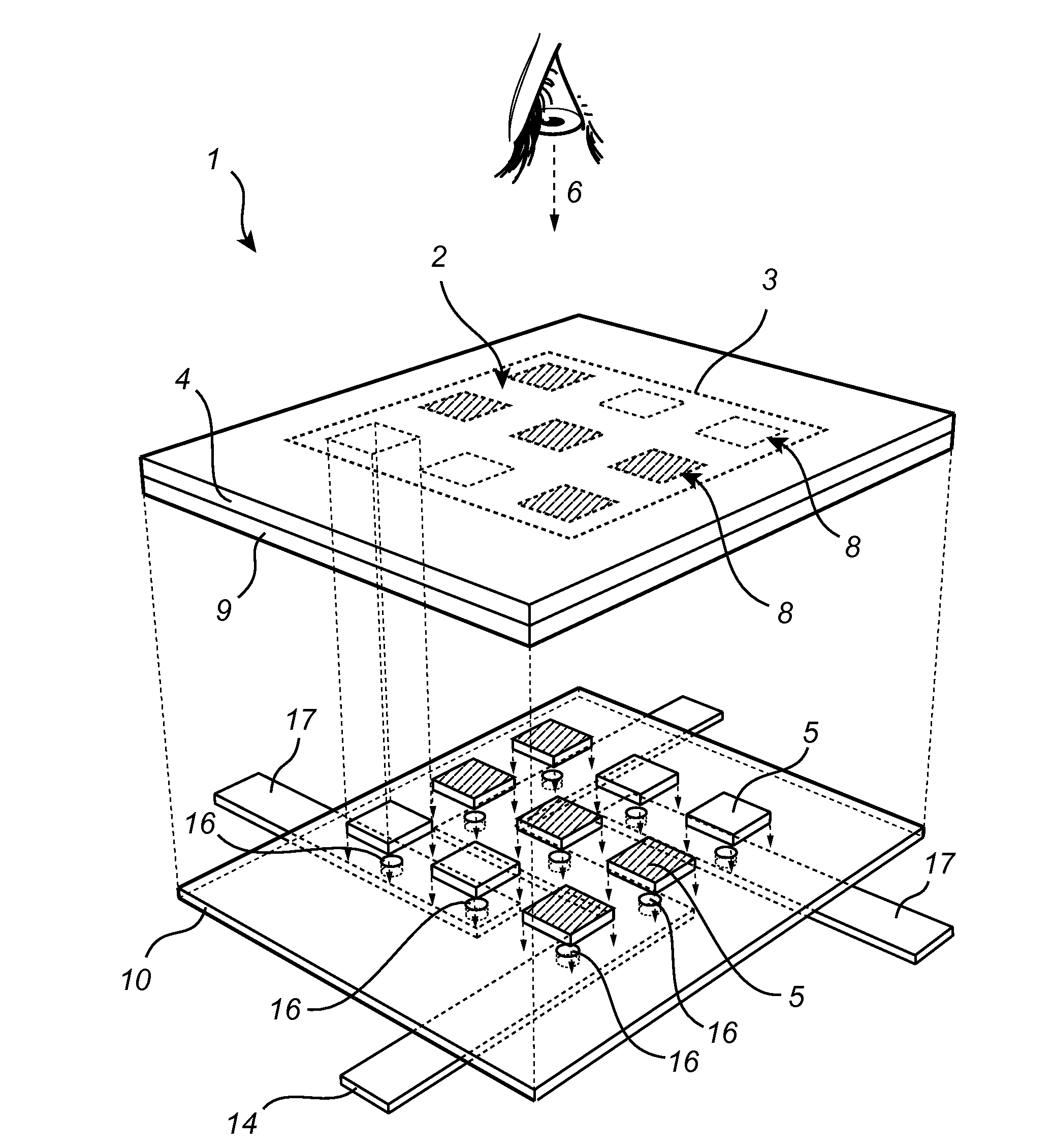
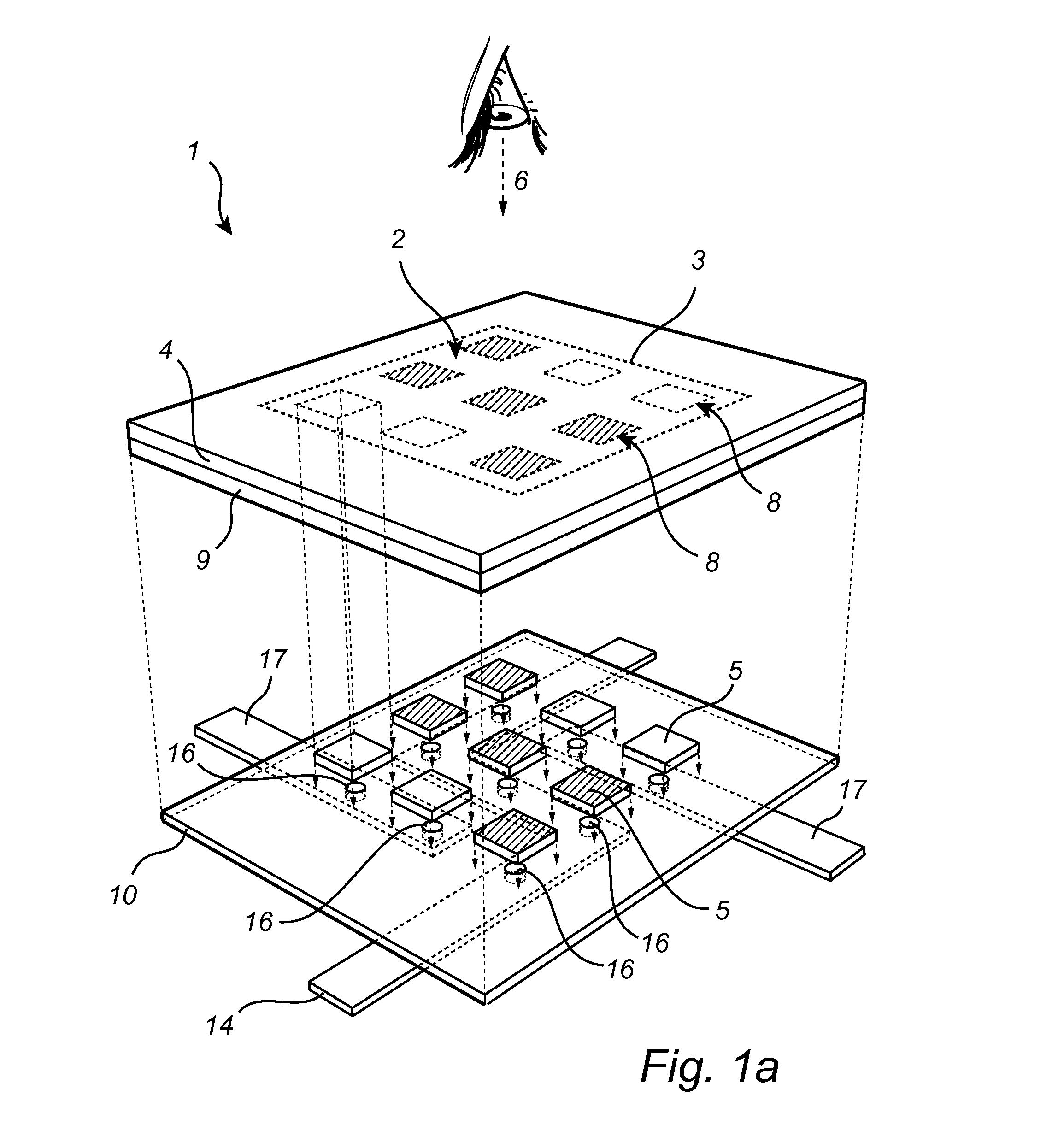
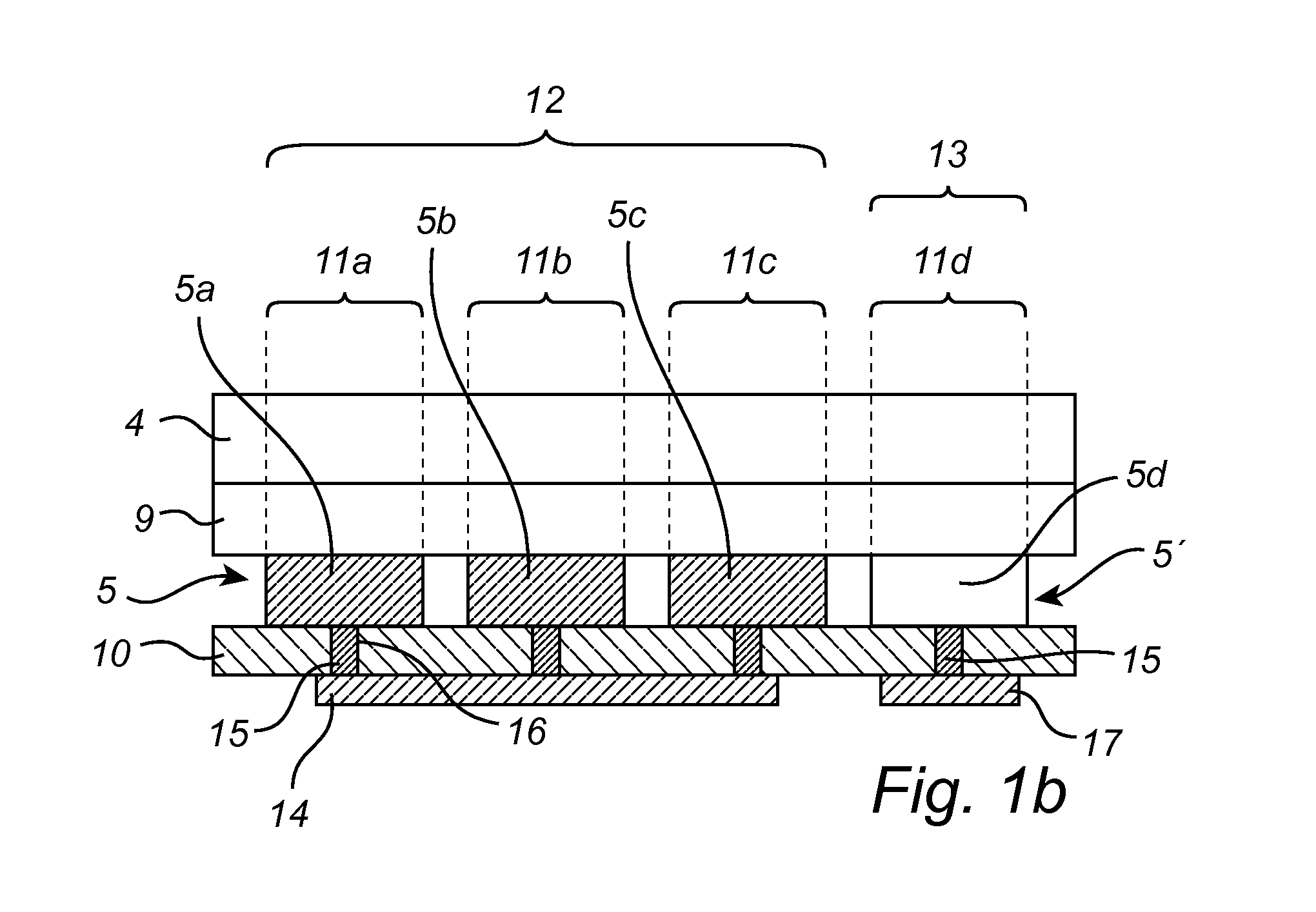
[0148]According to one example:

[0149]an insulating layer is provided with passages by means of laser drilling, the passages are arranged in orthogonal rows and columns and have a center-to-center distance of 1 mm, additionally each passage have a diameter of 70 μm;

[0150]a conductor comprising electronically conductive carbon is arranged in each of said passages;

[0151]a layer comprising PEDOT-PSS is printed on one side of said substrate, the PEDOT-PSS layer being divided into equilateral squares being 0.8 mm wide and having a center-to-center distance of 1 mm, wherein each square covers a respective one of said passages in the insulating layer;

[0152]one rectangular and uniform layer of electrolyte is printed on top of the PEDOT-PSS layer, such that it covers the squares beneath it;

[0153]a continuous layer comprising electronically conductive carbon is printed on the opposite side of the substrate, such that it in electronic contact with the respective connectors that are, in turn, co...


PUM

PropertyMeasurementUnit
thicknessaaaaaaaaaa
thicknessaaaaaaaaaa
thicknessaaaaaaaaaa

Abstract

A fixed image display device is disclosed, having an opaque insulating layer, a continuous electrolyte layer behind said insulating layer, a pixilated electrochemically active and electrochromic layer between the electrolyte layer and the insulating layer, and a pixilated electronically conductive counter electrode layer between the electrolyte layer and the insulating layer. The electrochromic layer and the counter electrode layer have a lateral arrangement, and are in ionic contact with each other. Moreover, the insulating layer includes passages having an electronic conductor. At least one continuous motif electrode segment arranged behind the insulating layer, and electronically connected to at least two pixel elements of the electrochromic layer via the electronic conductors; and at least one continuous background electrode segment arranged behind the insulating layer, and electronically connected to at least two pixel elements of the counter electrode layer via electronic conductors.

Description

PRIORITY STATEMENT[0001]This present application hereby claims priority under 35 U.S.C.§119 to European Application No. 12192052.4 filed Nov. 9, 2012, and hereby claims priority under 35 U.S.C. §119(e) to U.S. Provisional Application No. 61 / 724,362, filed Nov. 9, 2012, the entire contents of each of which are hereby incorporated herein by reference.FIELD OF THE INVENTION[0002]The present invention relates to electrochemically active organic fixed image display devices and the manufacturing of such devices. In particular, the present invention relates to printable, electrochemically active fixed image display devices based on organic electrochromic and electrochemically active materials, which display device is arranged to display, when activated, a predetermined fixed image in a display area of the display device, wherein the fixed image comprises at least one motif area and at least one background area which areas in combination define the fixed image visually perceived by the end ...

Claims


Application Information

Patent Timeline
Patent Type & Authority Applications(United States)
IPC IPC(8): G02F1/15
CPCG02F1/15G02F1/15165G02F1/155G02F2001/1557G02F2201/42
Inventor MALMSTROM, ANNA
Owner ACREO SWEDISH ICT
Features
  • Generate Ideas
  • Intellectual Property
  • Life Sciences
  • Materials
  • Tech Scout
  • Unparalleled Data Quality
  • Higher Quality Content
  • 60% Fewer Hallucinations
Learn More