Air conditioning indoor unit

Inactive Publication Date: 2014-05-15
DAIKIN IND LTD
View PDF4 Cites 11 Cited by
  • Summary
  • Abstract
  • Description
  • Claims
  • Application Information

AI Technical Summary

Benefits of technology

[0028]The air conditioning indoor unit pertaining to the first aspect can deliver the conditioned air more widely in the right and left direction while keeping the pressure loss of the conditioned air that is blown out low.
[0029]The air conditioning indoor unit pertaining to the second aspect can more reliably ensure the spread of the conditioned air in the right and left direction.
[0030]The air conditioning indoor unit pertaining to the third aspect can keep the total number of the air flow direction guide blades small.
[0031]The air conditioning indoor unit pertaining to the fourth aspect can spread the direction in which the conditioned air is supplied even more in the right and left direction.
[0032]The air conditioning indoor unit pertaining to the fifth aspect can keep the air on the room side from flowing in toward the right and left side walls of the air outlet.
[0033]The air conditioning indoor unit pertaining to the sixth aspect can supply the conditioned air even more widely in the right and left direction while keeping the flow of the conditioned air from coming away from the protruding curved surfaces.

Problems solved by technology

Conventionally, wall-mounted air conditioning indoor units have been required to blow out conditioned air more widely in the right and left direction from the air outlet because the position where the air outlet can be disposed is limited in comparison to ceiling-suspended air conditioners.

Method used


Image

  • Air conditioning indoor unit
  • Air conditioning indoor unit
  • Air conditioning indoor unit

Examples


Embodiment Construction

[0050]An air conditioning apparatus 1 serving as an embodiment will be described below with reference to the drawings.

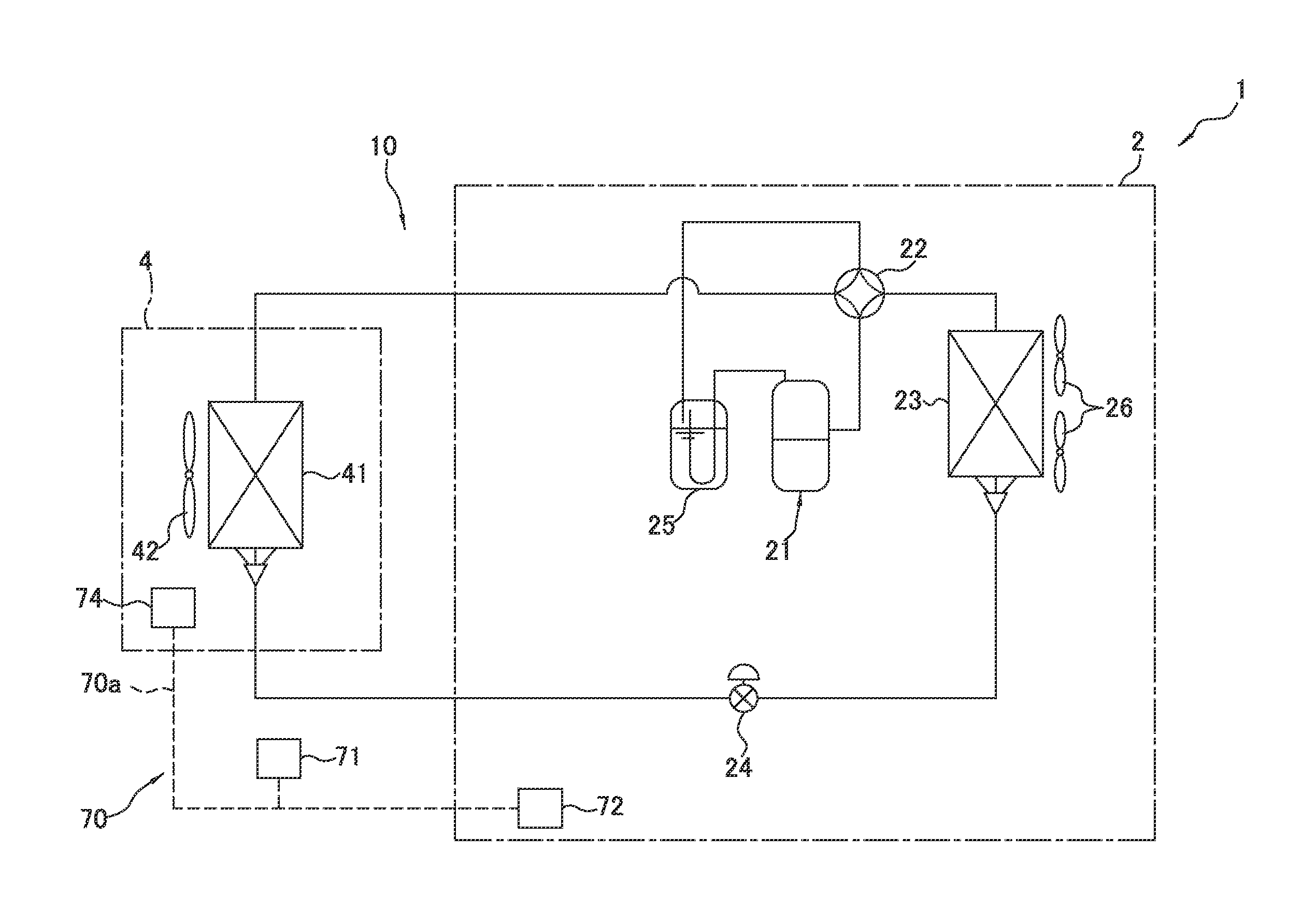
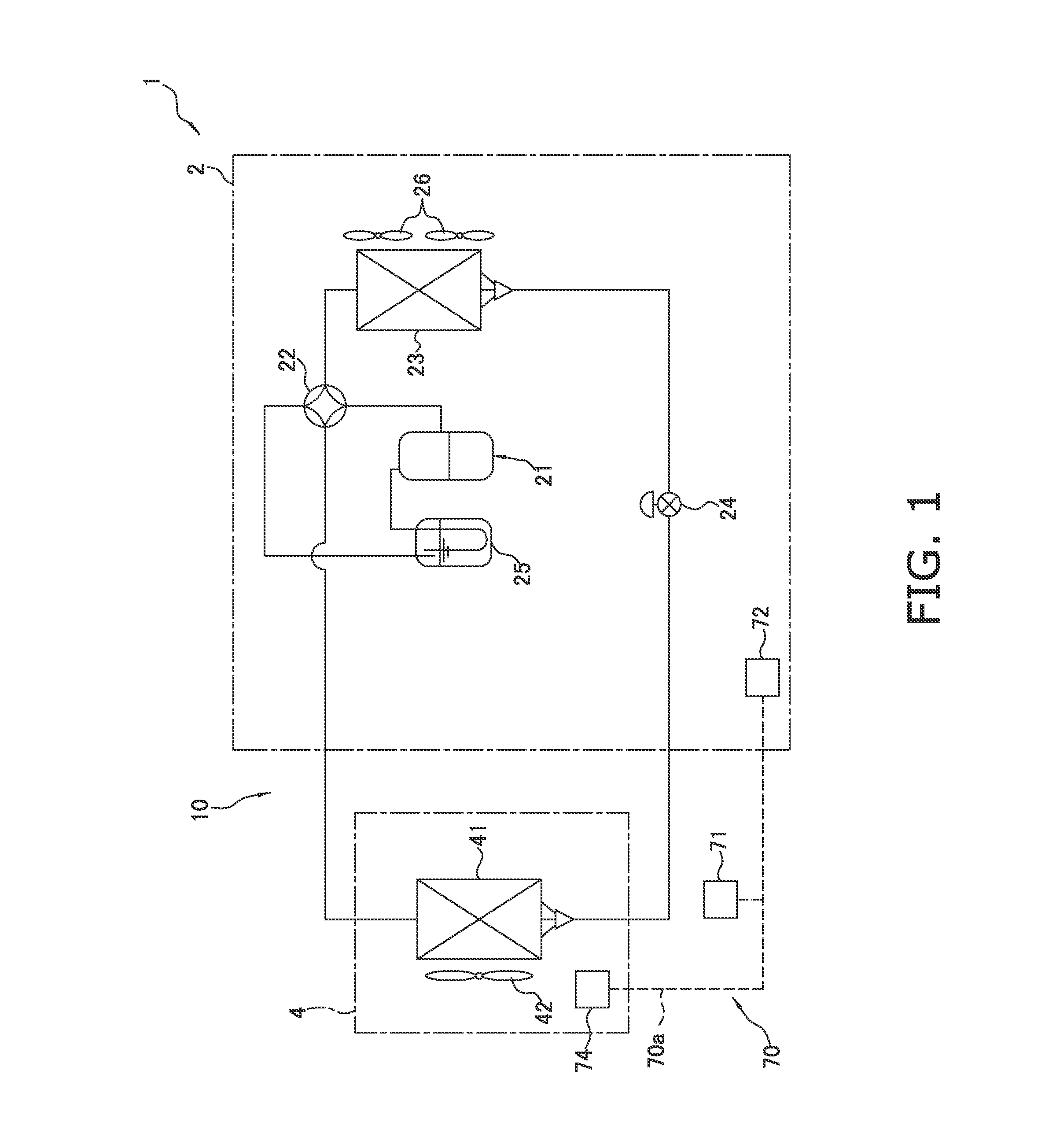
[0051]FIG. 1 is a refrigerant circuit diagram showing a refrigerant circuit 10 of the air conditioning apparatus 1.

(1) Schematic Configuration of Air Conditioning Apparatus 1

[0052]The air conditioning apparatus 1 has an air conditioning outdoor unit 2 serving as a heat source-side unit and an air conditioning indoor unit 4 serving as a utilization-side unit that are interconnected by refrigerant pipes, and the air conditioning apparatus 1 performs air conditioning of the space M which the utilization-side unit is placed. The air conditioning apparatus 1 has the refrigerant circuit 10, various types of sensors, and a control unit 70.

[0053]The refrigerant circuit 10 is equipped with a compressor 21, a four-way switching valve 22, an outdoor heat exchanger 23, an outdoor electromagnetic expansion valve 24, an accumulator 25, outdoor fans 26, an indoor heat exchanger 41,...


PUM


Abstract

A wall-mounted air conditioning indoor unit includes a casing, and an air flow direction adjustment unit with plural guide blades positioned between right and left side walls of the outlet passage of the casing. A first of the guide blades is positioned closest to a predetermined side wall of the right and left side walls. In a state in which the first guide blade is postured closer to the predetermined side wall as the first guide blade extends on a downstream side, first and second gaps are formed between first and second sections of the first guide blade and the predetermined side wall, respectively. The first section is part of an end portion of the first blade on the downstream side. The second section is outside the first section. The first gap is equal to or less than 10 mm. The second gap is greater than 10 mm.

Description

TECHNICAL FIELD[0001]The present invention relates to an air conditioning indoor unit.BACKGROUND ART[0002]Conventionally, wall-mounted air conditioning indoor units have been required to blow out conditioned air more widely in the right and left direction from the air outlet because the position where the air outlet can be disposed is limited in comparison to ceiling-suspended air conditioners.[0003]For example, the air conditioner described in patent document 1 (JP-A No. S62-10553) employs a structure where, focusing on the point that the right and left side walls of the air outlet obstruct the conditioned air from being blown out more widely in the right and left direction, the right and left side walls of the air outlet are curved in such a way that the right and left direction width of the air outlet expands in the direction in which the conditioned air is blown out. This air conditioner employing a shape in which the right and left side walls of the air outlet are expanded keep...

Claims


Application Information

Patent Timeline
Patent Type & Authority Applications(United States)
IPC IPC(8): F24F13/10
CPCF24F13/10F24F13/15F24F1/0011F24F2221/28F24F11/79
Inventor KAMADA, MASASHITERAOKA, HIRONOBUOKUDA, NORIYUKISHIGESAWA, TOORUYASUO, KOUICHIAKAI, TATSUHIKOKUIDA, KOUTAROU
Owner DAIKIN IND LTD
Why Eureka
Try Eureka