Steerable assembly for surgical catheter

a technology of surgical catheters and assembly parts, applied in the field of catheters, can solve the problems of affecting the operation, affecting the operation, and unable to permit the physician to control the distal end of the catheter, so as to achieve the effect of denying the surgeon the required degree of control

Active Publication Date: 2014-05-15
ABBOTT CARDIOVASCULAR
View PDF4 Cites 117 Cited by
  • Summary
  • Abstract
  • Description
  • Claims
  • Application Information

AI Technical Summary

Benefits of technology

[0012]The inventive concept thus described provides an advantageous solution which prevents the distal end of the catheter from being so flexible or “floppy” that it denies the surgeon the required degree of control. The inventive concept limits the extreme distal end of the catheter to having only one degree of bending freedom, and does not allow the distal end to bend in simply any direction—as may apply when it has two degrees of bending freedom. Under two degrees of bending freedom, the distal end would disadvantageously have the capability of changing position under the application of only slight external forces such as may naturally occur within the patient's anatomy through respiration and the like.
[0013]Furthermore, by arranging the wires in detents in accordance with the principles of the inventive concept, this tends to prevent the outcome that both wires may be relocated to only one side of the tube in the vicinity of a bend—an effect that may cause the wires to lose their ability to apply opposing forces over the whole length of the tube for bending the tube left

Problems solved by technology

However, problems persist in the art of steerable catheters in applications such as the foregoing.
At this point, a problem may arise in that the steerable portion of the catheter at the distal end does not permit the physician enough control over the tool attached to the distal end of the catheter.
Thus, just when a physician believes the tip of the catheter is in the correct place to conduct the intended procedure, the tip of the catheter may change its position without the physician applying any additional force via pullwires such as may be used to steer the catheter, and this

Method used


Image

  • Steerable assembly for surgical catheter
  • Steerable assembly for surgical catheter
  • Steerable assembly for surgical catheter

Examples


Embodiment Construction

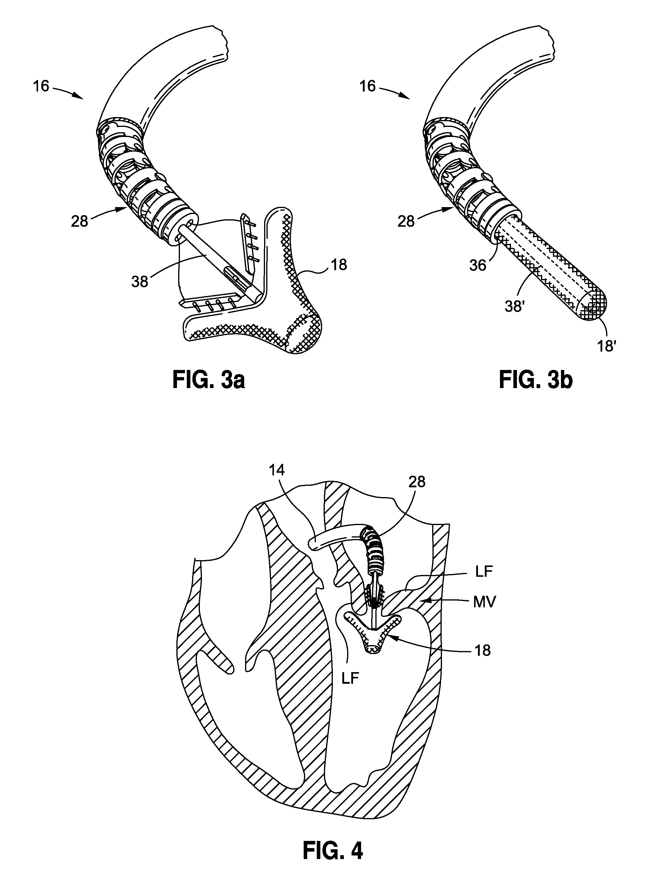
[0040]With reference to the figures, preferred embodiments of the invention are described. The specification discloses features of a bendable and steerable assembly that can be bent in compound and complex ways for greater maneuverability within the body and, ultimately, enhanced efficacy of the operative device carried by the bendable assembly, which, in some embodiments, may be a catheter, or may be configured to receive a catheter through a central bore. The illustrated and preferred embodiments disclose and describe these structures, systems, and techniques in relation to mitral valve repair, although the same may be used in conjunction with any procedure requiring complex maneuverability.

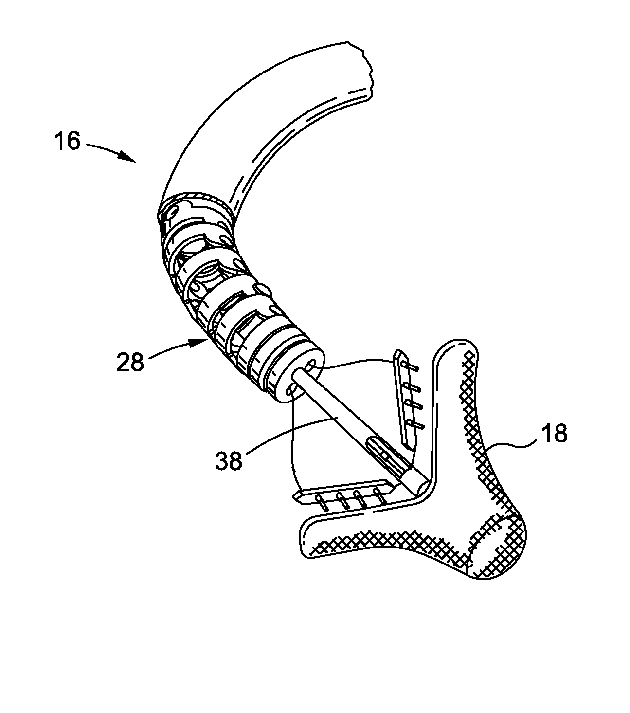
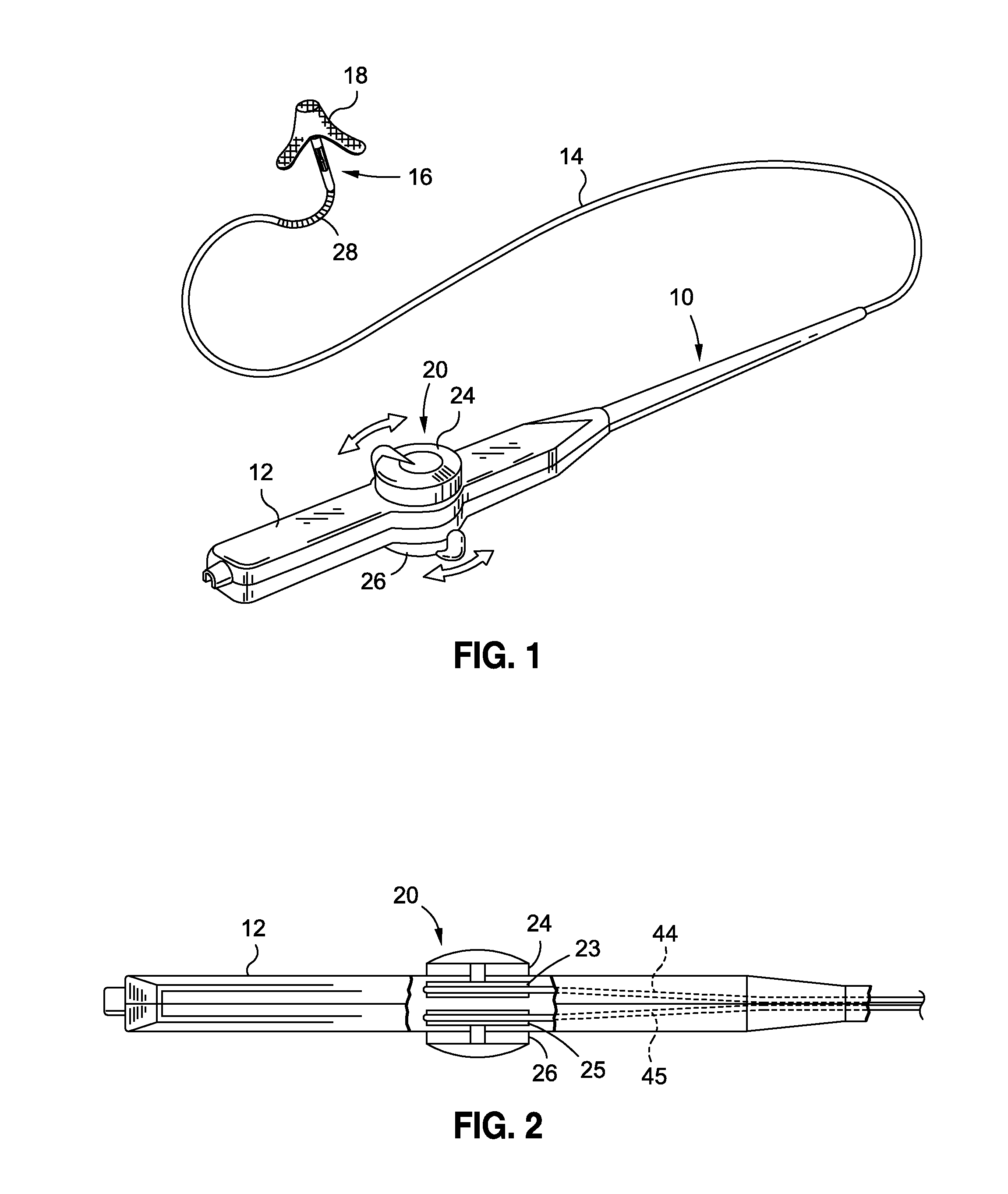
[0041]FIG. 1 shows a catheter 10, which includes features of the invention. The catheter 10 includes a handle 12 and a flexible tubular catheter body 14. In the illustrated and exemplified embodiment of the catheter, the distal region 16 may, for example, carry a clip device 18 for performing m...


PUM


Abstract

A catheter configured for intraluminal delivery to a location in the body of a patient, the catheter comprising a steerable assembly comprising a first segment connected to a second segment; the first segment comprises first and second cylindrical elements connected to each other by a first revolute joint in a first single plane; the second segment comprises third and fourth cylindrical elements connected to each other by a second revolute joint in a second single plane, wherein the first single plane and the second single plane are offset by an angle from each other.

Description

BACKGROUND[0001]This invention relates to catheters that can by steered by external controls. More particularly the invention relates to such catheters that can assume three dimensional curves.[0002]Modern medical procedures rely ever more upon minimally invasive access to organs and tissues of a patient, frequently via body lumens such as veins or arteries. A common feature of most such procedures is that a medical device may be carried at the distal tip of a catheter, or may be inserted to the tip of a steerable assembly, to a desired location in the body of a patient, where it may be activated. For example, one or more electrodes may be provided at the distal end of a catheter for purposes of tissue ablation; inflatable balloons may be provided for purposes of vessel expansion, or for separating tissue layers to create a space to perform a further procedure; blades or rotating burrs may be provided for purposes of clearing a blocked lumen; or, needles may be provided for injectin...

Claims


Application Information

Patent Timeline
IPC IPC(8): A61M25/01
CPCA61M25/0147A61M25/0141A61B1/008A61M25/0138A61B2017/00314A61M2025/0161A61B2017/00323A61B2017/00783A61F2/246
Inventor KABE, ARUNDHATI N.THORNTON, TROY L.WEISS, AARON M.
Owner ABBOTT CARDIOVASCULAR
Why Eureka
Try Eureka