Vehicle driving support apparatus

a technology for supporting apparatus and vehicles, which is applied in vehicle position/course/altitude control, braking system, instruments, etc., can solve the problems of low detection accuracy, inability to say that a driver necessarily travels at the center of a lane, etc., to achieve low detection accuracy of road shapes, suppress the start of approach prevention control, and reduce the effect of nois

Active Publication Date: 2014-05-15
NISSAN MOTOR CO LTD
View PDF32 Cites 41 Cited by
  • Summary
  • Abstract
  • Description
  • Claims
  • Application Information

AI Technical Summary

Benefits of technology

[0007]According to an aspect of the present invention, the start of approach prevention control is suppressed when detection accuracy of a road shape is low. Accordingly, performing of unnecessary approach prevention control (intervention by unnecessary approach prevention control) is reduced when the detection accuracy in detecting a road shape is low. As a result, it is possible to further suppress an uncomfortable feeling given to a driver when performing driving support for an obstacle rearward and sideward of the vehicle.

Problems solved by technology

However, for example, since drivers individually have preferences or habits for the travel position in a lane, it cannot be said that a driver necessarily travels at the center of a lane when the driver does not have an intention of lane change.
Accordingly, the detection of an intention of lane change depending on the operation of the direction indicator and the travel position in the lane may have low detection accuracy.
That is, even when a driver does not have an intention of approach to an obstacle, control for preventing the approach to the obstacle may intervene, which may give an uncomfortable feeling to the driver.

Method used


Image

  • Vehicle driving support apparatus
  • Vehicle driving support apparatus
  • Vehicle driving support apparatus

Examples


first embodiment

[0018]In this embodiment, an example will be described where a vehicle driving support apparatus is mounted on a rear-wheel-drive vehicle. In addition, a front-wheel-drive vehicle or a four-wheel-drive vehicle may be applied as a target vehicle. An EV vehicle or a hybrid vehicle may be applied.

(Configuration)

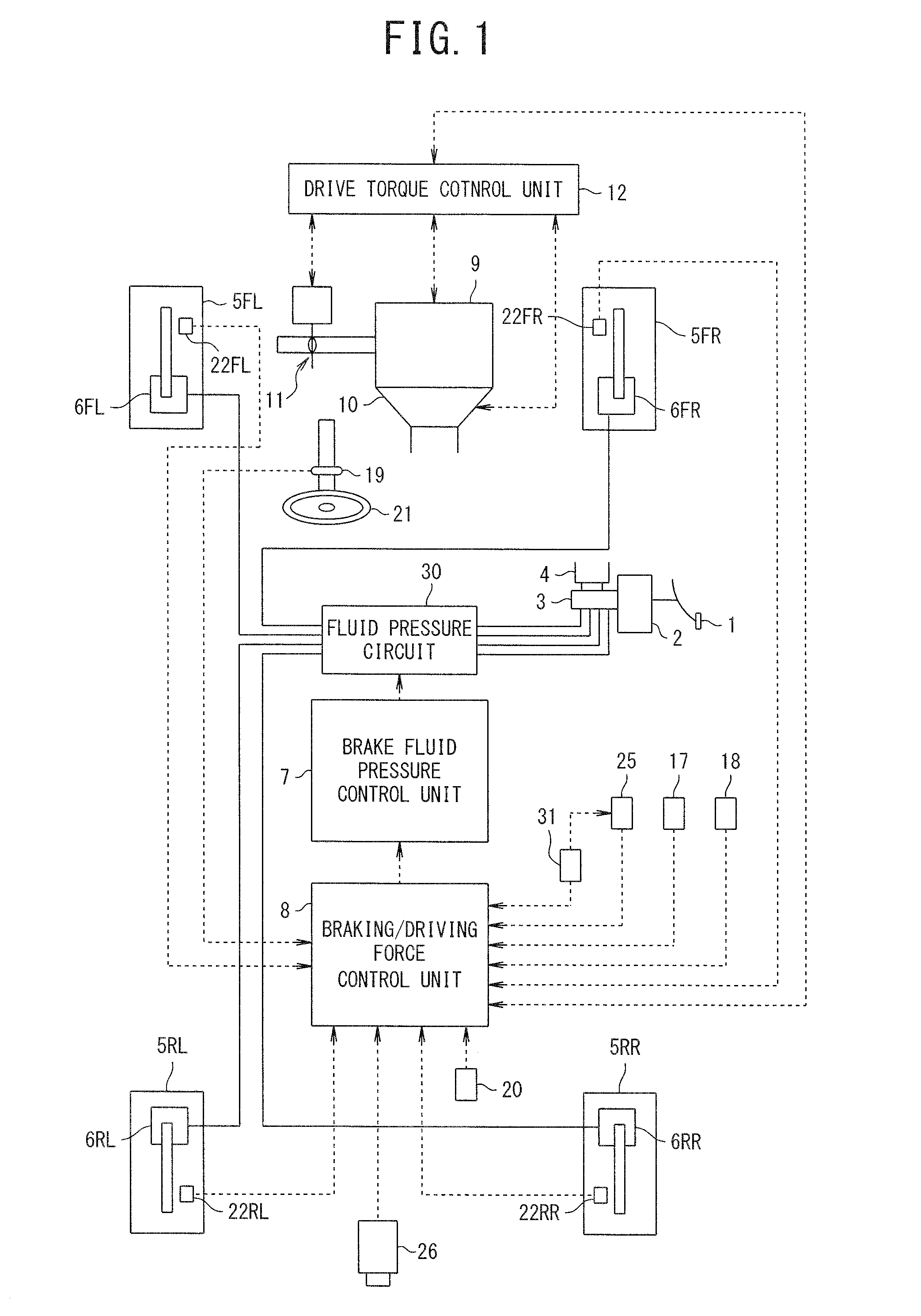
[0019]FIG. 1 is a diagram illustrating a schematic configuration of an apparatus according to this embodiment.

[0020]Reference numeral 1 in FIG. 1 represents a brake pedal. The brake pedal 1 is connected to a master cylinder 3 via a booster 2. Reference numeral 4 in FIG. 1 represents a reservoir.

[0021]The master cylinder 3 is connected to wheel cylinders 6FL to 6RR via a fluid pressure circuit 30. Accordingly, in a state where braking control is not operated, a brake fluid pressure is boosted up by the master cylinder 3 depending on the depression amount of the brake pedal 1 pressed by a driver. The boosted brake fluid pressure is supplied to the wheel cylinders 6FL to 6RR of whe...

second embodiment

[0158]A second embodiment will be described below with reference to the accompanying drawings. The same elements as in the above-mentioned embodiment will be referenced by the same reference numerals.

[0159]The basic configuration of this embodiment is the same as the first embodiment. In the second embodiment, a steering speed instead of the steering angle is used as the steering amount.

[0160]Processes different from those of the first embodiment will be described below.

[0161]In this embodiment, the processing procedure illustrated in FIG. 7 is performed instead of the processing procedure (FIG. 5) described in the first embodiment. The differences will be described below.

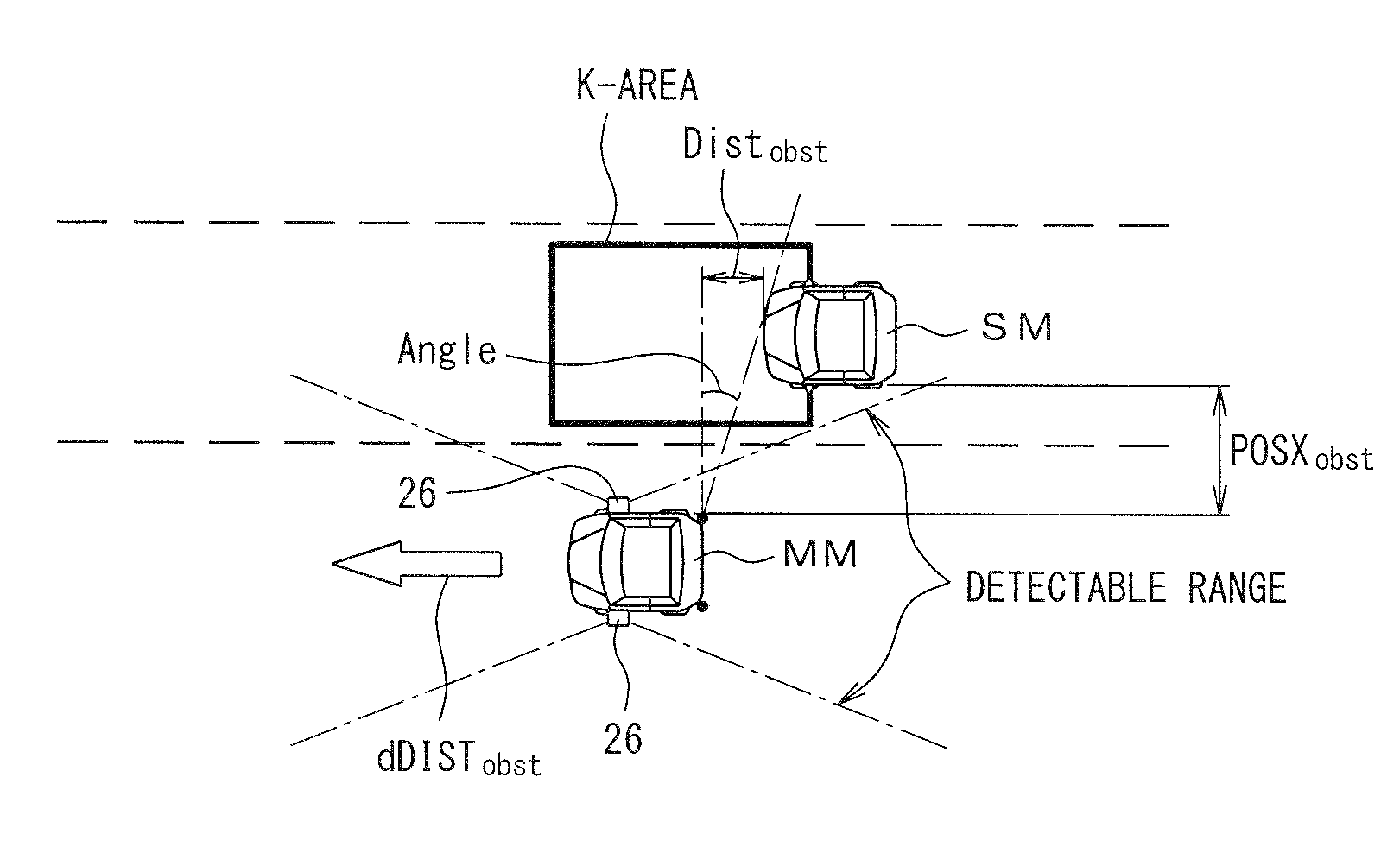
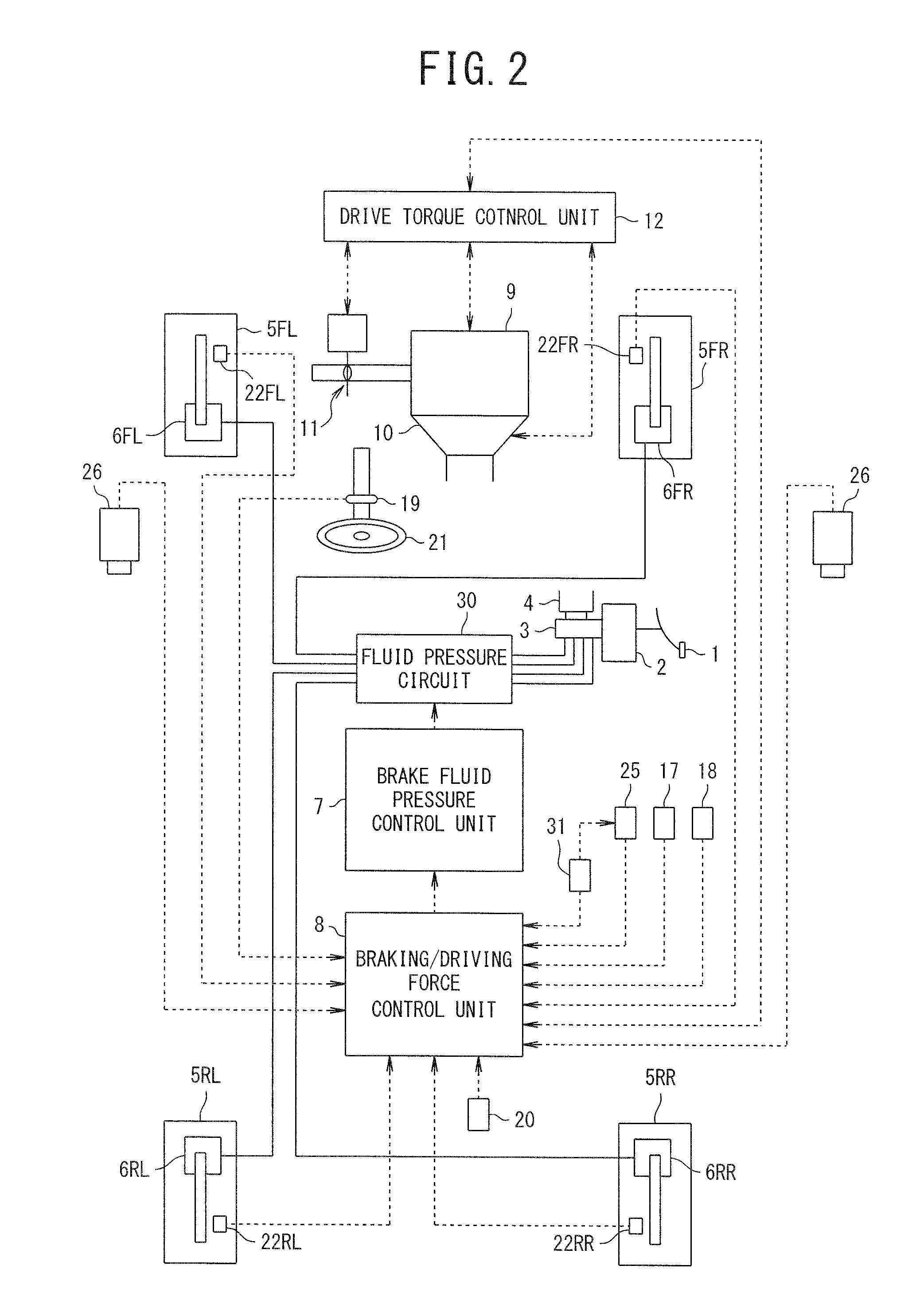
[0162]In the process of step S20a (process of detecting the obstacle SM), the obstacle SM is detected using the rear camera in the first embodiment. On the contrary, in the second embodiment, the configuration illustrated in FIG. 4 is employed and the obstacle SM is detected using millimeter wave radars (24L and 24...

third embodiment

[0184]A third embodiment will be described below with reference to the accompanying drawings. The same elements as in the above-mentioned embodiment will be referenced by the same reference numerals.

[0185]The basic configuration of this embodiment is the same as the first embodiment.

[0186]In the third embodiment, it is determined whether or not the control should start on the basis of a future transverse position predicted based on the steering instead of using the actual steering amount. Specifically, the control is performed on the basis of a transverse position variation of the vehicle MM after a predetermined time Ts.

[0187]Steps S40b to S120b and S140b are performed as illustrated in FIG. 8 instead of steps S40 to S120 and S140 described in the first embodiment.

[0188]The processes of the different steps will be described below.

[0189]In step S40b, a neutral yaw rate φ′ path for maintaining a traveling path is calculated using the traveling curvatureβ. The neutral yaw rate φ′ path...


PUM


Abstract

A braking / driving force control unit determines whether or not the driver has a intention of lane change on the basis of the detected road shape and the steering amount. The braking / driving force control unit detects an obstacle which is an obstacle present rearward and sideward of the vehicle. The braking / driving force control unit determines whether approach prevention control for preventing an the vehicle from approaching to the obstacle should start, when it is determined that the driver has the intention of lane change and the obstacle is detected, and performs the approach prevention control for supporting prevention of the vehicle from approaching to the obstacle when it is determined that the control should start. At this time, the braking / driving force control unit determines detection accuracy of the road shape ahead of the vehicle and suppresses the determination of the start of the control when the detection accuracy is low.

Description

TECHNICAL FIELD[0001]The present invention relates to a vehicle driving support technique of supporting a driver's driving to prevent a vehicle from approaching to an obstacle located rearward and sideward of the vehicle.BACKGROUND ART[0002]For example, a technique disclosed in Patent Document 1 is known as a conventional vehicle driving support apparatus. In the technique disclosed in Patent Document 1, when a driver's intention of lane change is detected and an obstacle is present rearward and sideward of a vehicle, approach to the obstacle is informed to the driver to prevent the approach to the obstacle. At this time, in the technique disclosed in Patent Document 1, the driver's operation of a direction indicator is detected, a position of the vehicle in a lane in the transverse direction (the position of a rightmost lane or leftmost lane) is detected, and the driver's intention of lane change is detected when the operating direction of the direction indicator is matched with th...

Claims


Application Information

Patent Timeline
Patent Type & Authority Applications(United States)
IPC IPC(8): G08G1/16
CPCG08G1/166B60T7/22B60T17/22G08G1/167B60W50/14B60W30/18163B62D15/0265B60T8/17557B60T2201/08B60T2210/24B60T2210/34B60T2210/36B60W2552/00
Inventor HAYAKAWA, YASUHISANISHIMAKI, SHUHEI
Owner NISSAN MOTOR CO LTD
Why Eureka
Try Eureka