Deployment apparatus and method of deploying an underwater power generator

a technology of underwater power generators and equipment, which is applied in the field of underwater power generator equipment and methods of underwater power generator deployment, can solve the problems of affecting the deployment and installation of the turbine, affecting the accuracy of the deployment vessel, and affecting the installation and maintenance of the turbine. achieve the effect of facilitating the accurate positioning of the deployment vessel

Active Publication Date: 2014-05-22
ATLANTIS RESOURCES CORP PTE LTD
View PDF10 Cites 3 Cited by
  • Summary
  • Abstract
  • Description
  • Claims
  • Application Information

AI Technical Summary

Benefits of technology

The technical effects of the patent are as follows: 1. A ladder frame arrangement with stiles and rungs facilitates positioning of the power generating main body. 2. A hot stab connection connects the hydraulic line to the power generating main body for powering other services. 3. An alignment device facilitates quick and accurate alignment of connectors during recovery of the power generating main body. 4. A dynamic positioning system facilitates accurate positioning of the deployment vessel without the use of an anchor.

Problems solved by technology

The generators are generally difficult to install on valuable sites because powerful marine currents at those valuable sites flow all the time, or most of the time.
Generally speaking, forces generated by the currents are very high, increasing the stresses on, and hence the weight of, deployment components.
This hampers deployment and installation of the turbine.
Furthermore, the underwater power generators, when deployed, are sited at least tens of metres under the water surface which makes deployment of the underwater power generators difficult and expensive.
Accurate siting and positioning of the underwater power generator relative to other generator components, and relative to prevailing tidal currents is difficult when much of the major equipment for use in the deployment is above the surface of the water body, well away from the bed of the water body.

Method used


Image

  • Deployment apparatus and method of deploying an underwater power generator
  • Deployment apparatus and method of deploying an underwater power generator
  • Deployment apparatus and method of deploying an underwater power generator

Examples


Embodiment Construction

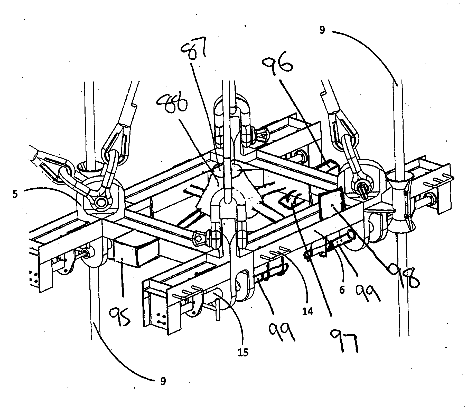
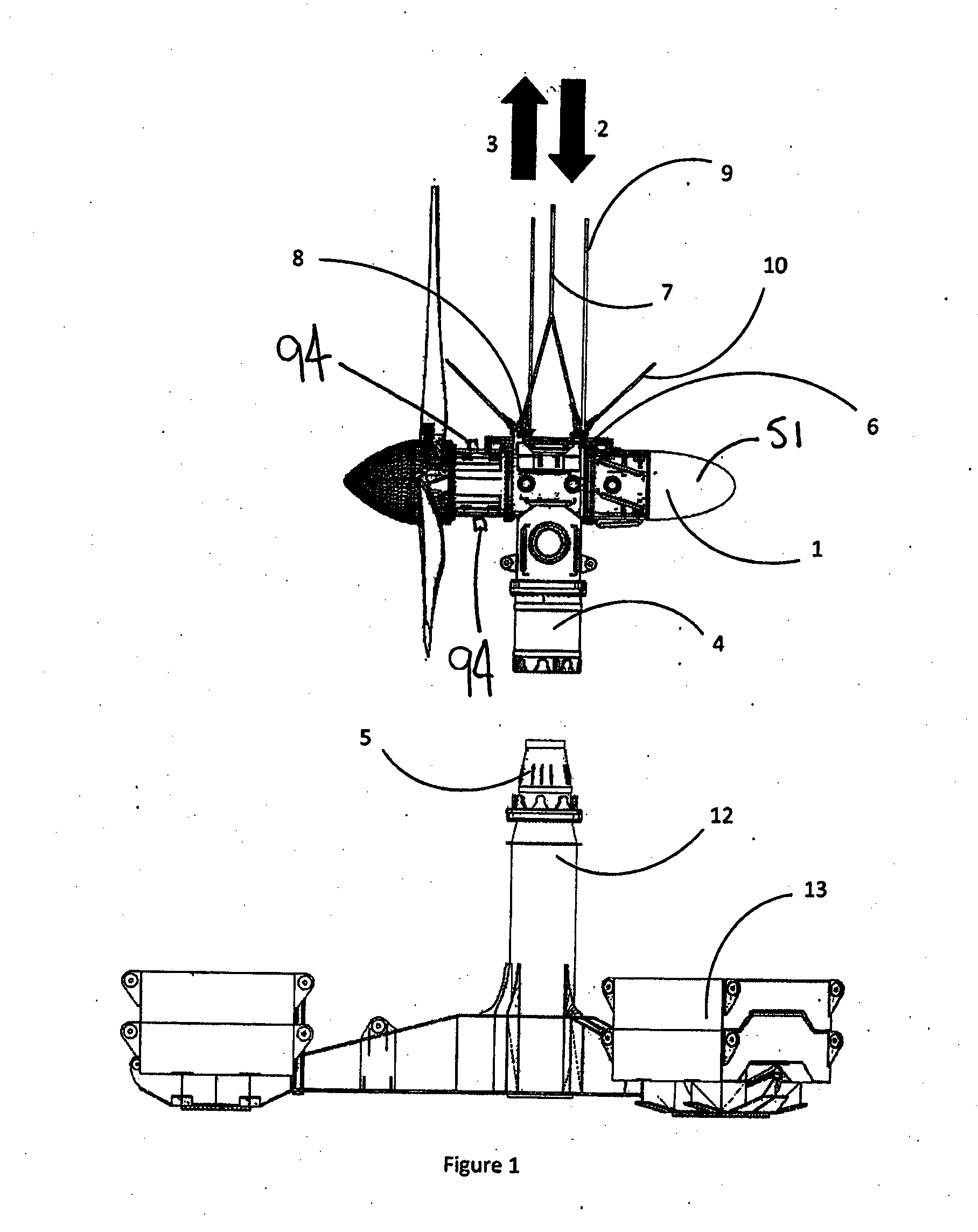
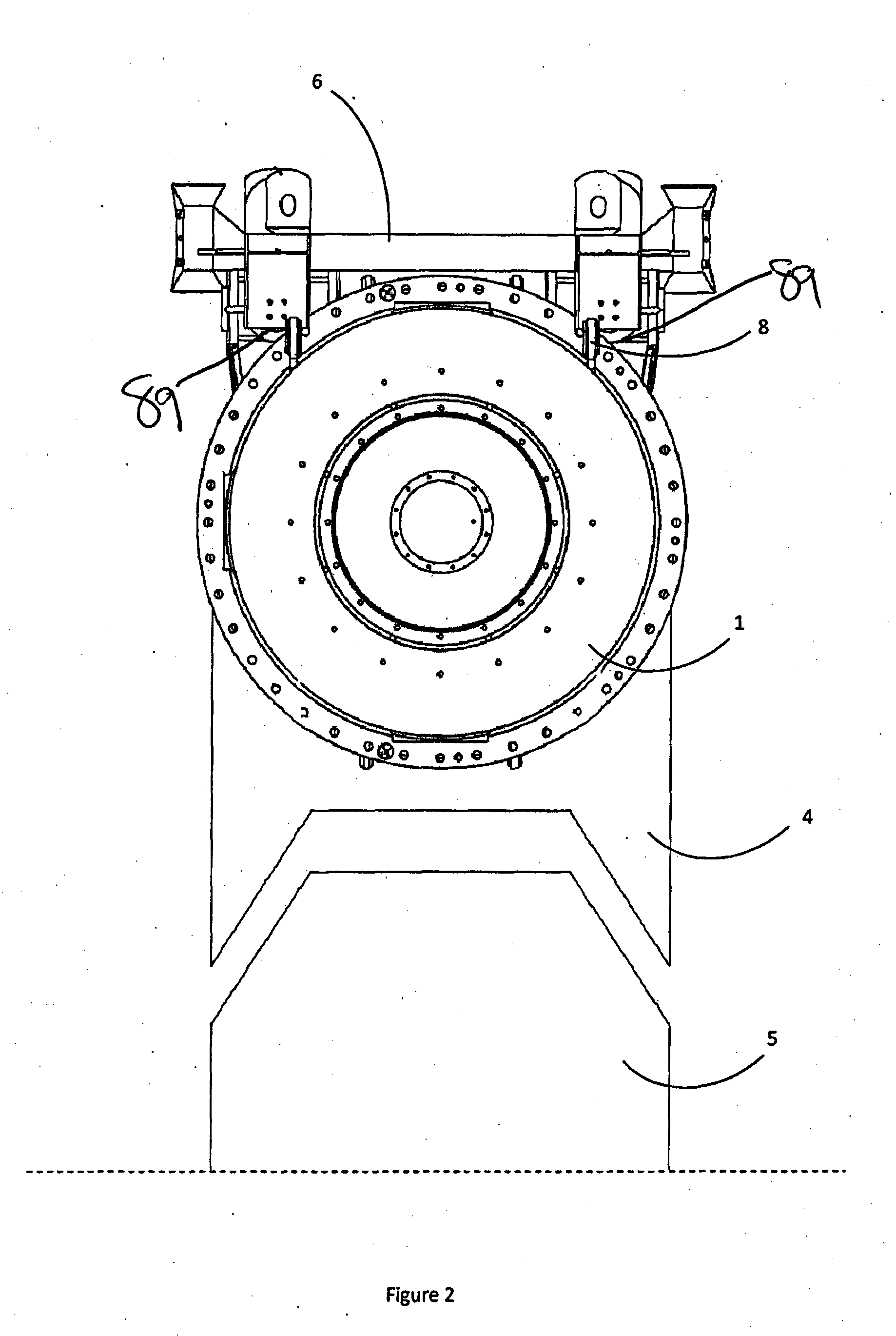
[0051]Referring to the drawings there is shown a deployment apparatus 50 for deploying an underwater power generator having a power generating main body 1. The power generating main body 1 when deployed, is disposed on a pylon 12 which itself is disposed on the bed of a body of water. The power generating main body 1 is in the form of a sealed nacelle 51 which houses power generating equipment such as for example rotor, shaft, bearings, gearbox, electrical generator, variable speed drive (VSD), monitoring equipment, sensors and inverters / converters. The deployment apparatus 50 includes a frame 6 adapted for releasable connection to the power generating main body 1, and to that end the frame 6 includes one or more connectors 60 for releasably connecting to the power generating main body 1.

[0052]The connectors 60 are disposed on a base region 75 of the frame and are remotely operable between engaged and disengaged positions by virtue of hydraulic rams connected to a hydraulic line 16 ...


PUM


Abstract

A deployment apparatus is described. The deployment apparatus is for deploying an underwater power generator having a power generating main body from a deployment vessel disposed on the surface of a body of water onto a pylon disposed on the bed of the body of water and the deployment apparatus includes: a frame including one or more connectors disposed on a base region of the frame, the connectors for releasable connection to catches disposed on an upper region of the power generating main body, the connectors being remotely operable between a connected position in which the connectors are engaged with the catches and a disconnected position in which the connectors are disengaged from the catches; and one or more cameras disposed on the frame for providing visual guidance to the vessel of the position of the underwater power generator relative to the pylon. A method for deployment of the underwater power generator is also described.

Description

FIELD OF THE INVENTION[0001]The present invention relates generally to apparatus for deployment of underwater power generators, and methods of deploying underwater power generators.BACKGROUND OF THE INVENTION[0002]Underwater power generators convert the energy of flowing marine and water currents into usable power, which is generally electrical power. The generators are generally difficult to install on valuable sites because powerful marine currents at those valuable sites flow all the time, or most of the time.[0003]Generally speaking, forces generated by the currents are very high, increasing the stresses on, and hence the weight of, deployment components. This hampers deployment and installation of the turbine.[0004]Furthermore, the underwater power generators, when deployed, are sited at least tens of metres under the water surface which makes deployment of the underwater power generators difficult and expensive. Accurate siting and positioning of the underwater power generator...

Claims


Application Information

Patent Timeline
IPC IPC(8): B66C1/66E02B17/04F03B13/10E02B9/08
CPCB66C1/10B66C13/08F03B13/10F05B2230/61F05B2240/97B66C1/108Y02E10/20Y02P70/50Y02E10/30B66C1/66E02B9/00E02B17/04B63C7/16F04D29/607E02B9/08
Inventor BLAXLAND, DREWRIGG, DAVID
Owner ATLANTIS RESOURCES CORP PTE LTD
Why Eureka
Try Eureka