Multi-mode Multi-coupling Multi-protocol Ubiquitous Wireless Power Transmitter

a multi-protocol, ubiquitous technology, applied in the direction of transformers, electromagnetic waves, inductances, etc., can solve the problems of weak power coupling linkage between power receivers wireless power receivers that cannot receive sufficient power to power up, etc., to achieve effective transmission of power

Inactive Publication Date: 2014-05-22
WIPQTUS
View PDF3 Cites 306 Cited by
  • Summary
  • Abstract
  • Description
  • Claims
  • Application Information

AI Technical Summary

Benefits of technology

[0018]The tank circuit of the variable matching circuit, the switch network, and the control logic circuit of the wireless power transmitter are configured to tune the power transmission based on the power coupling linkage between the wireless power transmitter and the wireless power receiver. The strength of the field linkage between the wireless power transmitter and the wireless power receiver may be strongly coupled, weakly coupled, critically coupled or over-coupled based on the three dimensional separation and alignment between the centers of the first circuit, size of the first circuit, etc. The wireless power transmitter tunes its power transmission to compensate for the strength of the field linkage between the wireless power transmitter and the wireless power receiver to transmit power effectively to the wireless power receiver.

Problems solved by technology

For example, when the wireless power receiver is first placed on the wireless power transmitter, the power coupling linkage between them may not be strong enough and the wireless power receiver may not be receiving sufficient power to power up.
A non-multi-coupling wireless power transmitter does not adapt itself so when the power coupling linkage is below the designed limit, the wireless power receiver will not receive sufficient power to power up or if its powered up, it may not be able to deliver the full requested power to its load as it is not getting the required power from the wireless power transmitter.

Method used


Image

  • Multi-mode Multi-coupling Multi-protocol Ubiquitous Wireless Power Transmitter
  • Multi-mode Multi-coupling Multi-protocol Ubiquitous Wireless Power Transmitter
  • Multi-mode Multi-coupling Multi-protocol Ubiquitous Wireless Power Transmitter

Examples


Embodiment Construction

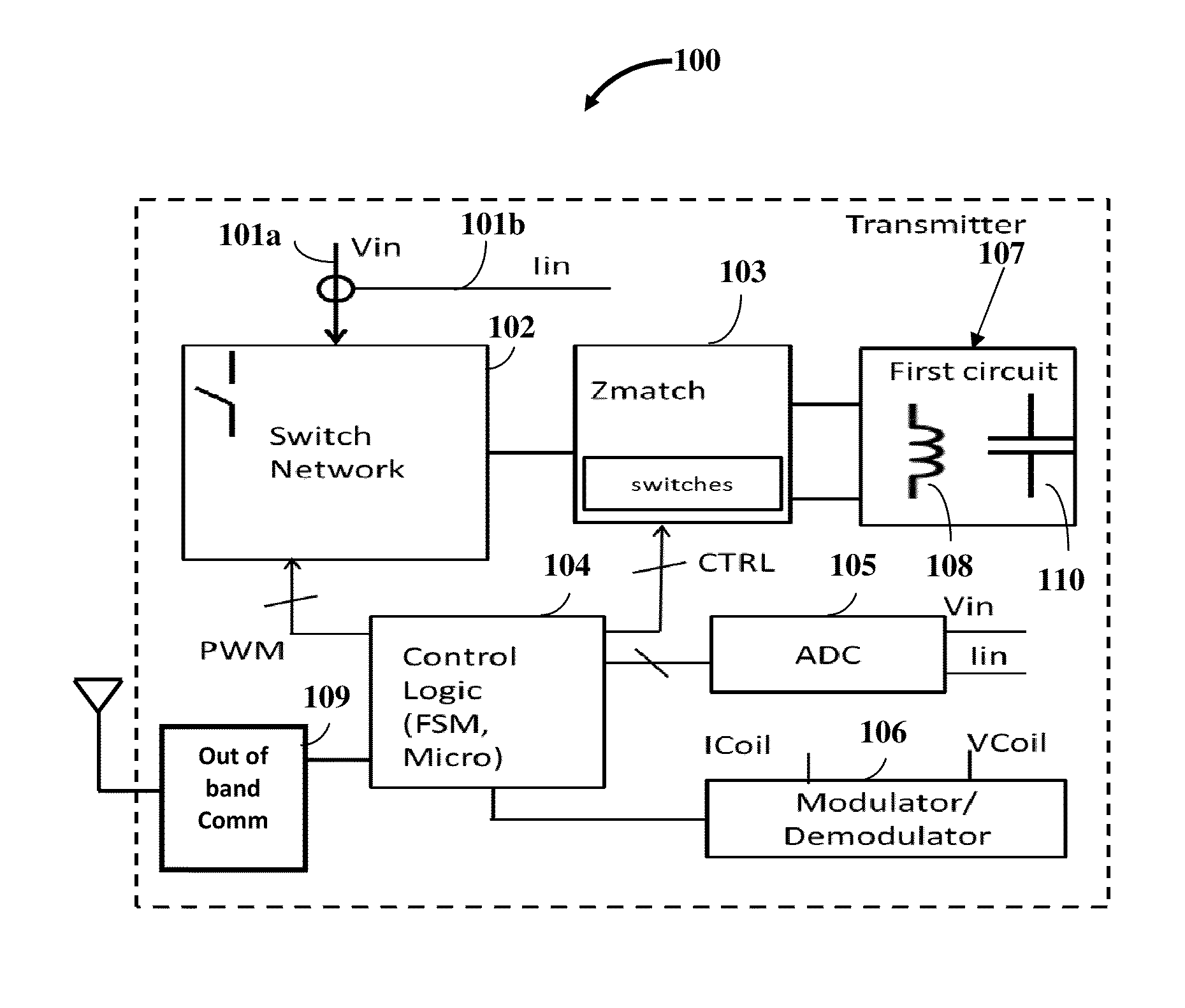
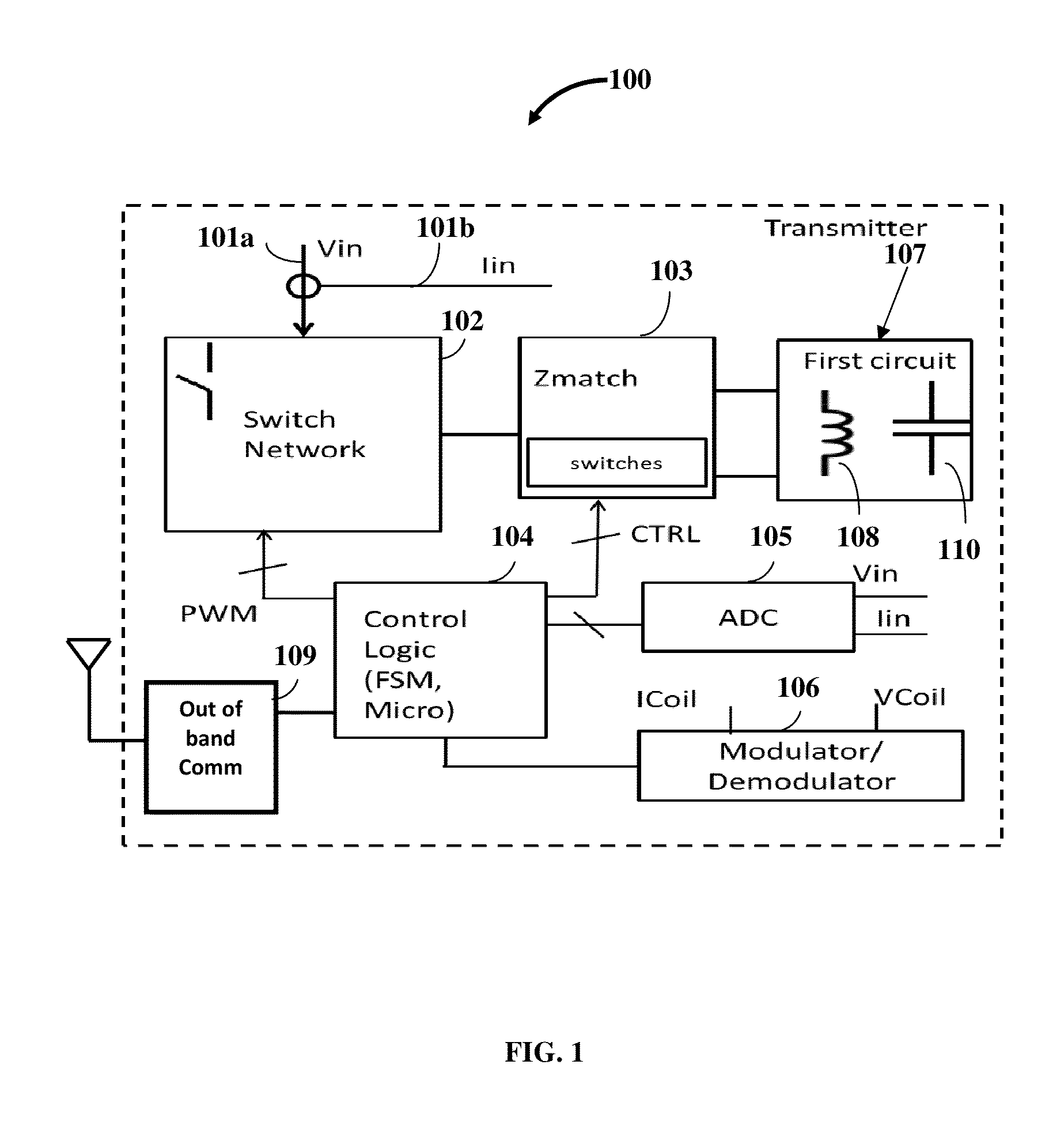
[0035]Disclosed herein is a multi-mode multi-coupling multi-protocol wireless power transmitter 100 exemplarily illustrated in FIG. 1, herein referred to as a “wireless power transmitter” that transmits power to a wireless power receiver (not shown) in a power transfer mode and a wireless power protocol matching that of the wireless power receiver. The wireless power transmitter 100 disclosed herein comprises a first circuit 107. The first circuit 107 comprises one or more inductors 108 and one or more capacitors 110. The first circuit 107 is configured to transmit power to the wireless power receiver via a magnetic field or an electric field. The magnetic field power transfer mode and the electric field power transfer mode represent the multiple power transfer modes of the wireless power transmitter 100.

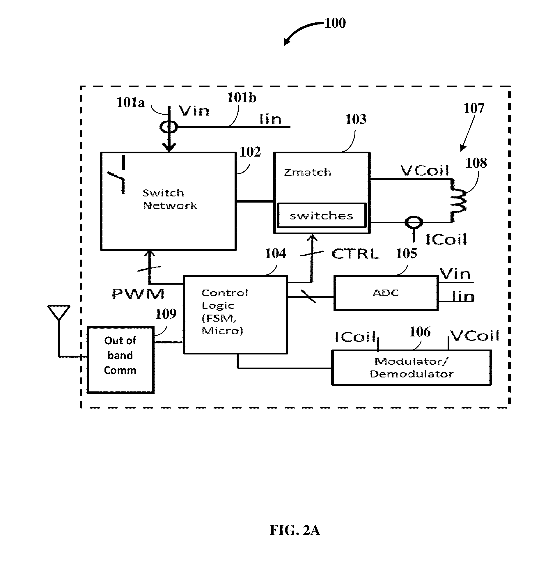
[0036]FIG. 2A exemplarily illustrates a schematic diagram of a multi-mode multi-coupling multi-protocol wireless power transmitter 100 configured to emanate power via a magnetic fie...


PUM


Abstract

A multi-mode multi-coupling multi-protocol wireless power transmitter (WPT) and its embodiments transmit power to a wireless power receiver (WPR) in a power transfer mode (PTM) and a wireless power protocol (WPP) of the WPR. A first circuit of the WPT includes inductors or capacitors emanating power via a magnetic field or electric field PTM respectively. The WPT sequentially parses a test condition to identify a PTM, a power coupling linkage (PCL) between the WPT and the WPR, and a WPP of the WPR. The WPT identifies a match if the PTM of the first circuit and the WPP of the switch network, the variable matching circuit, a modulator/demodulator block or an out-of-band communication block, and a control logic circuit of the WPT match the PTM and the WPP of the WPR to transmit power to the WPR based on the match.

Description

CROSS REFERENCE TO RELATED APPLICATIONS[0001]This application claims the benefit of the following patent applications:[0002]1. Provisional patent application No. 61 / 679,910 titled “Multi-mode Multi-protocol Wireless Power Transmitter”, filed in the United States Patent and Trademark Office on Aug. 6, 2012.[0003]2. Provisional patent application No. 61 / 730,068 titled “Multi-mode Multi-protocol Wireless Power Transmitter”, filed in the United States Patent and Trademark Office on Nov. 27, 2012.[0004]The specifications of the above referenced patent applications are incorporated herein by reference in their entirety.BACKGROUND[0005]From a technology perspective, the wireless power world is very fragmented. Wireless power can be delivered via magnetic inductive mode or electrostatic capacitive mode. In the magnetic inductive mode, the wireless power systems are configured to operate either at a resonant fixed operating point or in a non-resonant variable operating regime. The resonant s...

Claims


Application Information

Patent Timeline
Patent Type & Authority Applications(United States)
IPC IPC(8): H02J17/00
CPCH02J17/00H02J7/0042H02J50/05H02J50/80H02J50/90H02J50/10H02J50/402H02J50/12
Inventor SANKAR, GANAPATHYSINGH, MANJIT
Owner WIPQTUS
Why Eureka
Try Eureka