Fuel cell stack
a fuel cell and stack technology, applied in the field of fuel cell stacks, can solve the problems of non-uniform temperature in the power generation area, inability to sufficiently supply coolant, and the coolant supplied from the pair of coolant supply passages to the buffer tends to flow through the buffer non-uniformly, so as to suppress local degradation or stagnation of water, reduce pressure, and simple structure
- Summary
- Abstract
- Description
- Claims
- Application Information
AI Technical Summary
Benefits of technology
Problems solved by technology
Method used
Image

Examples
first embodiment
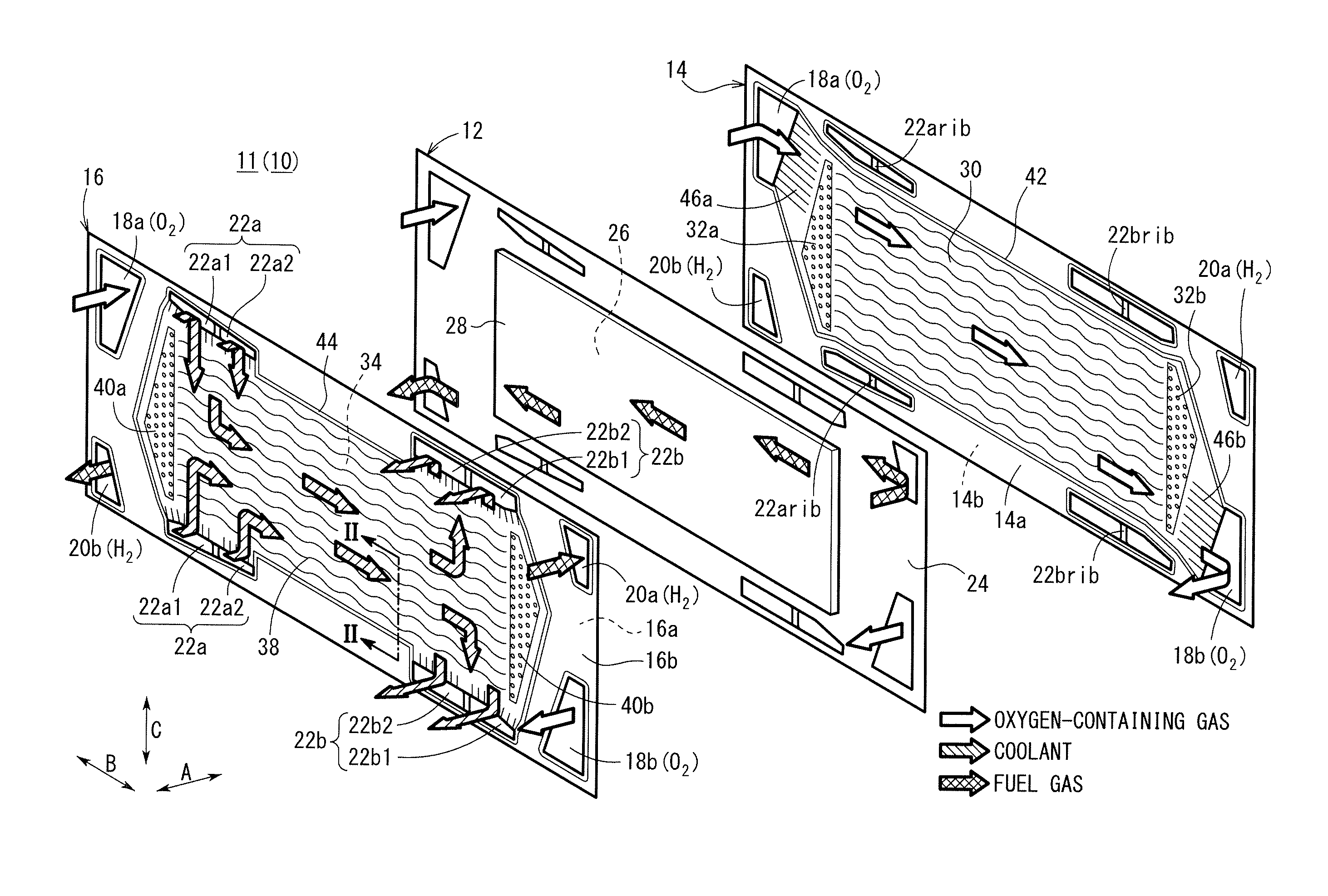
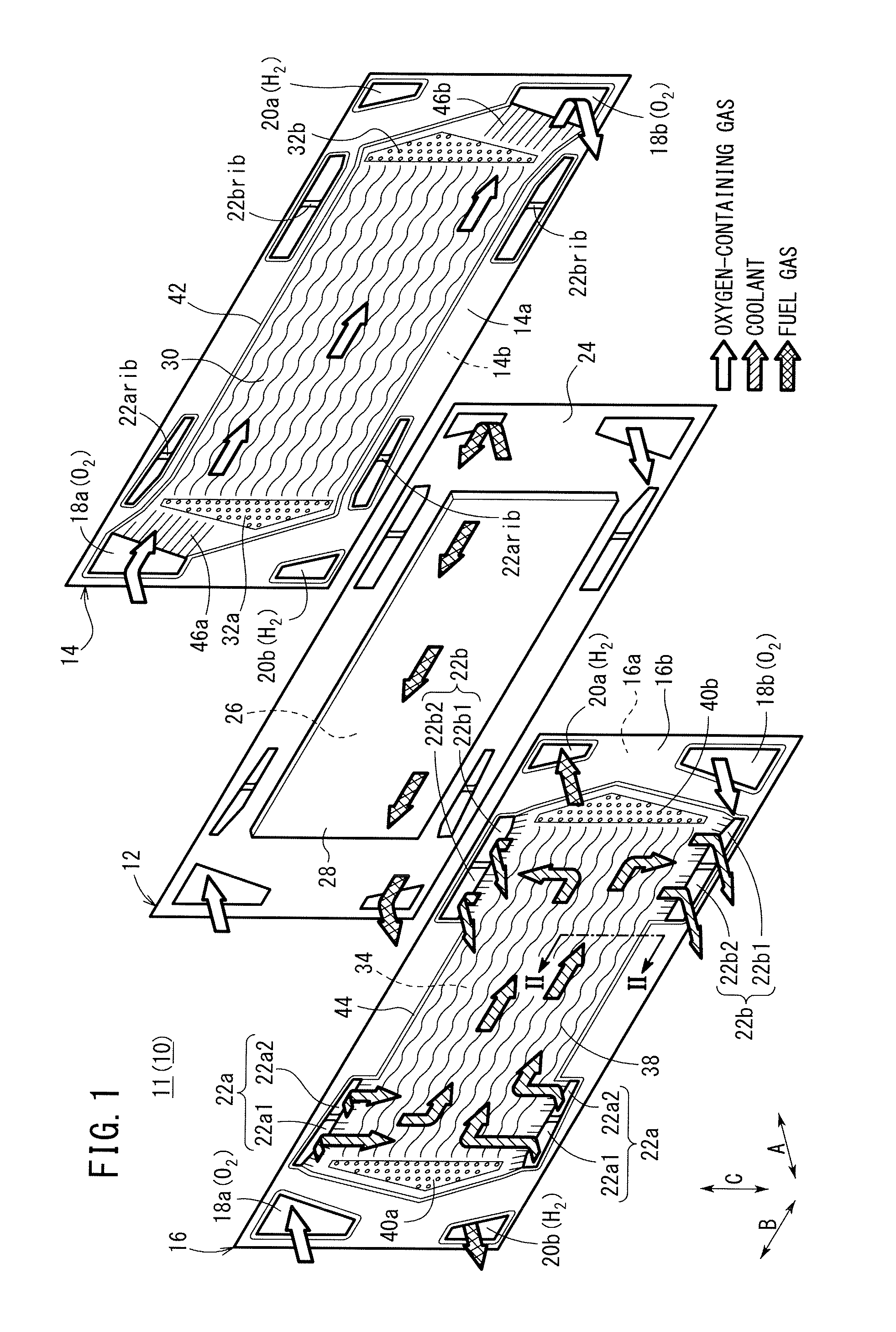
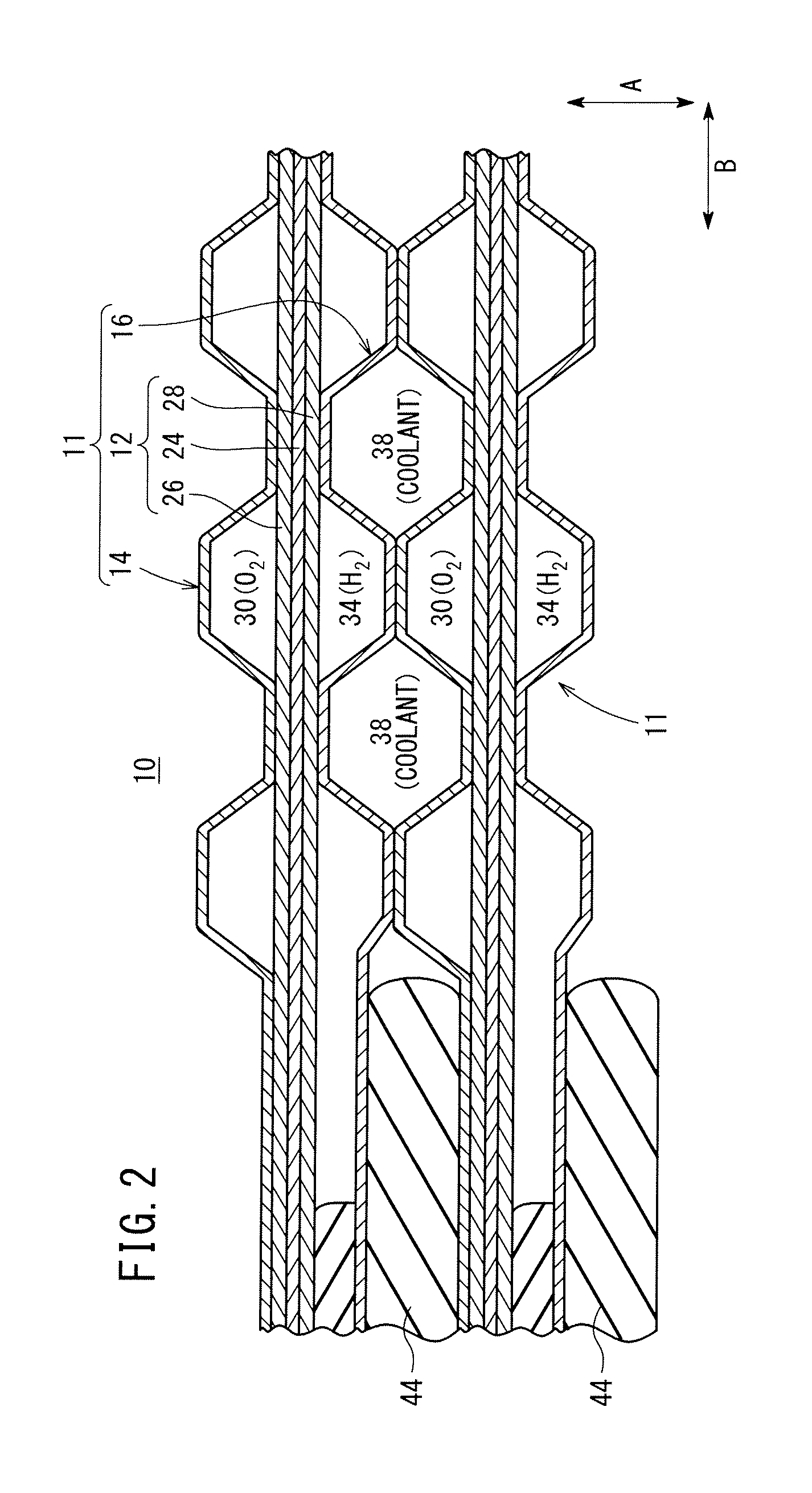
[0042]As shown in FIGS. 1 and 2, a fuel cell stack 10 according to the present invention is formed by stacking a plurality fuel cells 11 together upright in a direction indicated by an arrow A (such that electrode surfaces are oriented in parallel with the vertical direction). Each of the fuel cells 11 includes a membrane electrode assembly 12 and a cathode side separator 14 and an anode side separator 16 sandwiching the membrane electrode assembly 12.
[0043]For example, the cathode side separator 14 and the anode side separator 16 are thin metal separators made of metal plates such as steel plates, stainless steel plates, aluminum plates, plated steel sheets, or metal plates having anti-corrosive surfaces by surface treatment. The metal separators have rectangular surfaces, and are formed by corrugating metal thin plates by press forming to have a corrugated shape in cross section and a wavy or serpentine form on the surface. Alternatively, instead of the metal separators, carbon me...
third embodiment
[0096]In the third embodiment, as shown in FIG. 9, the coolant supply passage 22a is divided into the first area 22a1 and the second area 22a2 in the direction indicated by the arrow B by the rib 78arib. In the structure, a larger quantity of coolant is supplied to one of the first area 22a1 and the second area 22a2 having the lower pressure loss, i.e., having the larger cross sectional area. Therefore, simply by providing the rib 78arib at a desired position, it becomes possible to supply the coolant to the entire coolant flow field 38 uniformly.
[0097]Specifically, the opening area of the first area 22a1 is larger than the opening area of the second area 22a2, i.e., the pressure loss in the first area 22a1 is lower than the pressure loss in the second area 22a2.
[0098]In this regard, for comparison of the distribution state of the coolant supplied to the coolant flow field 38, structure without the rib 78arib (conventional example a) and structure having the rib 78arib (example a of...
fourth embodiment
[0104]As shown in FIG. 12, a fuel cell stack 90 according to the present invention is formed by stacking a plurality of fuel cells 91 together upright in a direction indicated by an arrow A (such that electrode surfaces are oriented in parallel with the vertical direction). Each of the fuel cells 91 includes a membrane electrode assembly 92 and a cathode side separator 94 and an anode side separator 96 sandwiching the membrane electrode assembly 92.
[0105]A slope 98a is provided in the first area 22a1 for decreasing the cross sectional area of the opening in a direction closer to the inlet buffer 40a. The slope 98a is inclined in a direction away from the inlet buffer 40a toward the horizontal direction indicated by the arrow B.
[0106]As shown in FIG. 13, inlet connection channels 100au1, 100au2 are formed adjacent to the coolant supply passage 22a on the upper side, and inlet connection channels 100ad1, 100ad2 are formed adjacent to the coolant supply passage 22a on the lower side.
[0...
PUM
 Abstract
Description
Claims
Application Information
 - R&D
- Intellectual Property
- Life Sciences
- Materials
- Tech Scout
- Unparalleled Data Quality
- Higher Quality Content
- 60% Fewer Hallucinations
Browse by: Latest US Patents, China's latest patents, Technical Efficacy Thesaurus, Application Domain, Technology Topic, Popular Technical Reports.
© 2025 PatSnap. All rights reserved.Legal|Privacy policy|Modern Slavery Act Transparency Statement|Sitemap|About US| Contact US: help@patsnap.com