Thermistor and method of constructing a thermistor

a technology of thermistor and thermistor body, which is applied in the direction of machines/engines, nuclear engineering, transportation and packaging, etc., can solve the problems of time-consuming manual approach, inconvenient and accurate laser ablation prior to soldering, and inability to achieve the effect of reducing the cost of laser ablation

Inactive Publication Date: 2014-05-29
AMPHENOL THERMOMETRICS
View PDF0 Cites 1 Cited by
  • Summary
  • Abstract
  • Description
  • Claims
  • Application Information

AI Technical Summary

Benefits of technology

[0004]According to an aspect of the invention, a method of constructing a thermistor includes forming a semiconductor ceramic substrate; coating a surface of the substrate with contact material; applying a solder mask on the contact material, the applying including applying the solder mask to one or more portions of the contact material to leave an exposed area without the solder mask and a masked area with the solder mask; and trimming the contact material at the masked area to adjust a resistance of the thermistor.

Problems solved by technology

While the process does not cause any problem with respect to physical connection of the leads to the contact, it can present other issues related to additional thermal changes and trimming requirements.
Trimming the contact surface (reducing contact size) to adjust the resistance (increase resistance value) has presented issues with regard to convenience and accuracy, among other factors.
However, since as noted above, thermal changes due to the soldering operation will affect resistance, laser ablation prior to soldering is somewhat inefficient with respect to the overall production of the thermistor.
However, this manual approach is time consuming and not readily automated.
Finally, although laser ablation through the solder (rather than prior to the soldering process) has been considered, the varying depth of solder across the face of the contact surface makes this approach impracticable.

Method used


Image

  • Thermistor and method of constructing a thermistor
  • Thermistor and method of constructing a thermistor
  • Thermistor and method of constructing a thermistor

Examples


Embodiment Construction

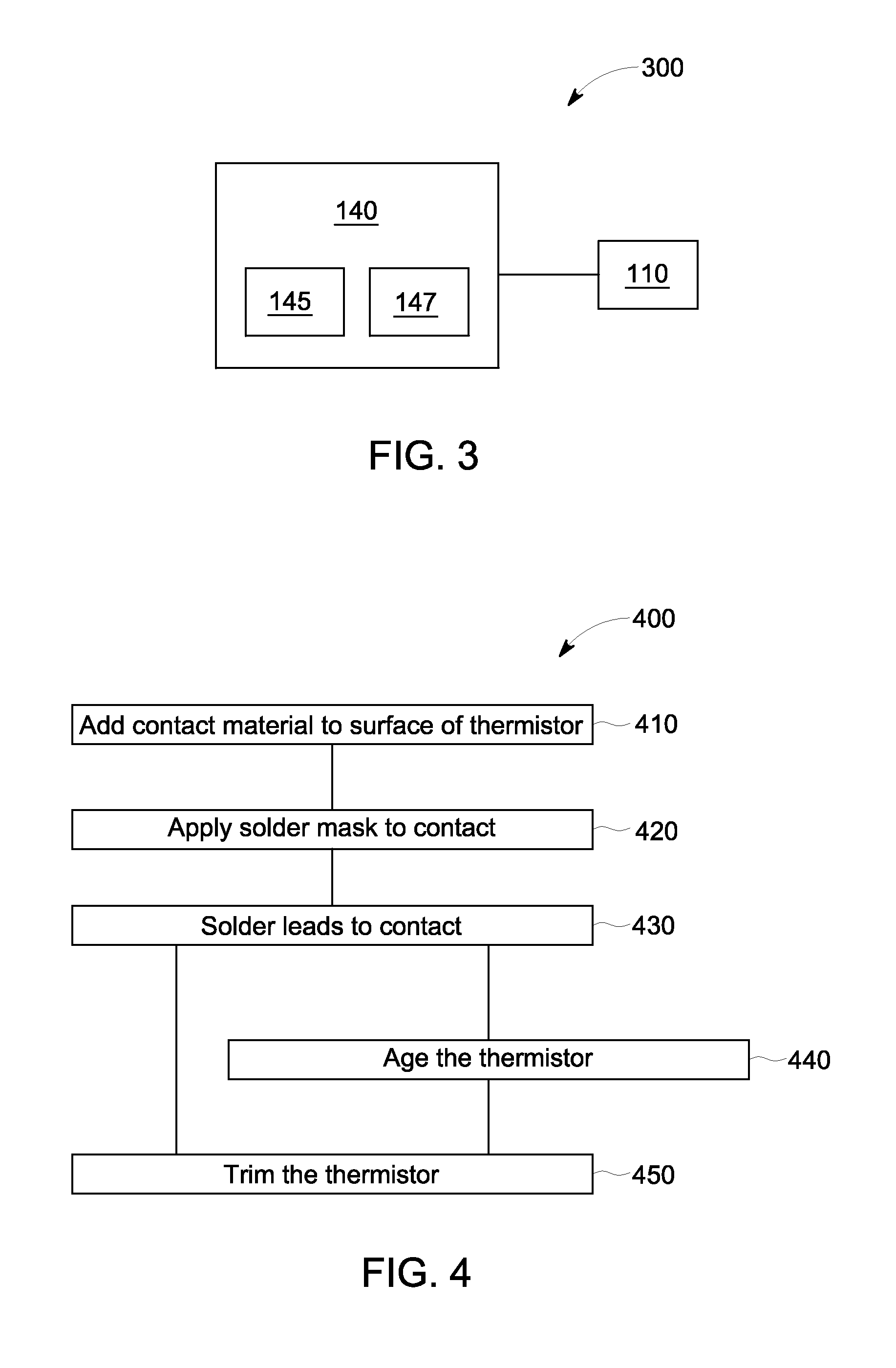
[0012]The method and system described in the embodiments herein address the issues, noted above, in trimming a thermistor to adjust resistance values. The following is a detailed description of one or more embodiments of the disclosed system and method presented herein by way of exemplification and not limitation with reference to the figures.

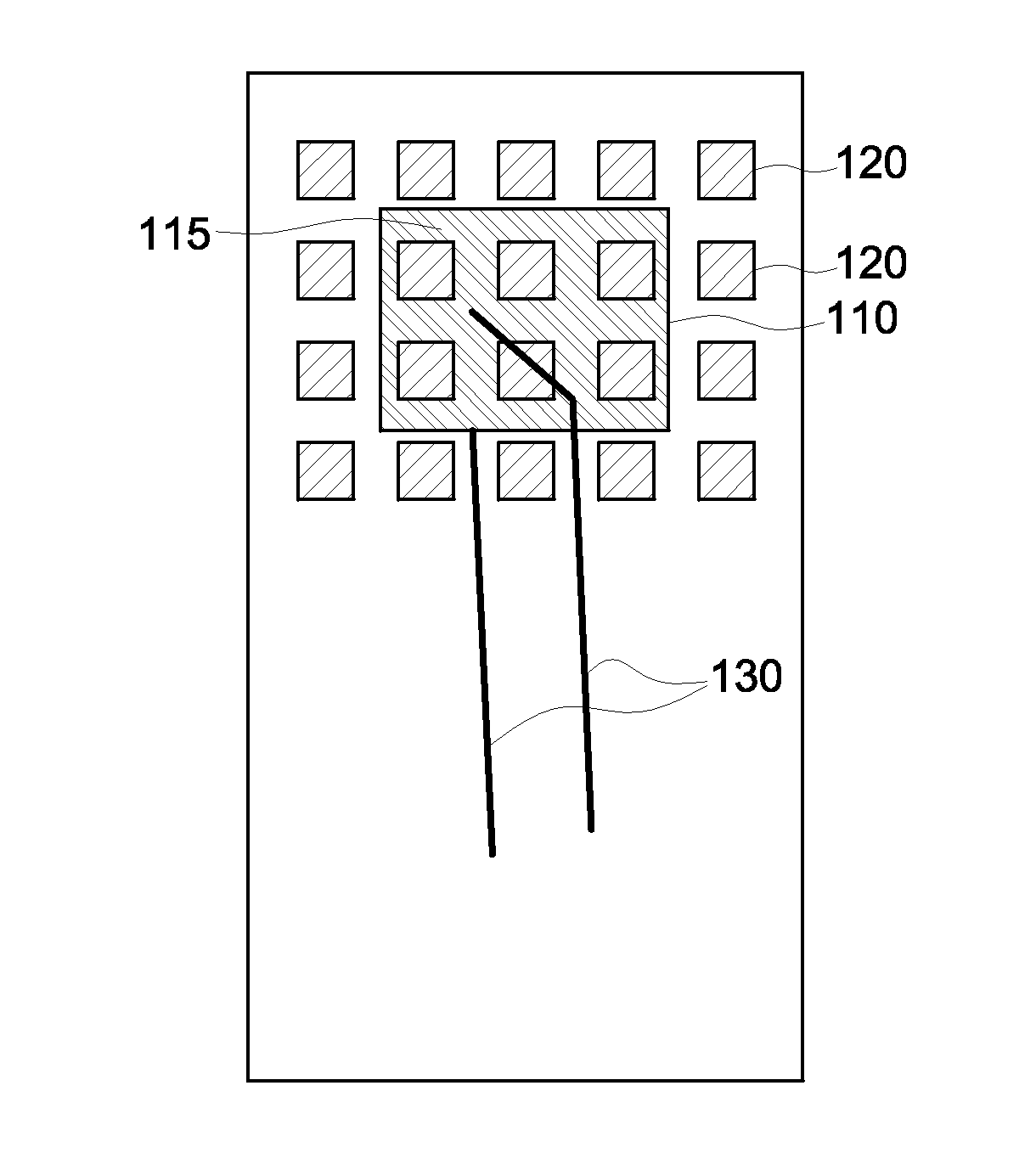
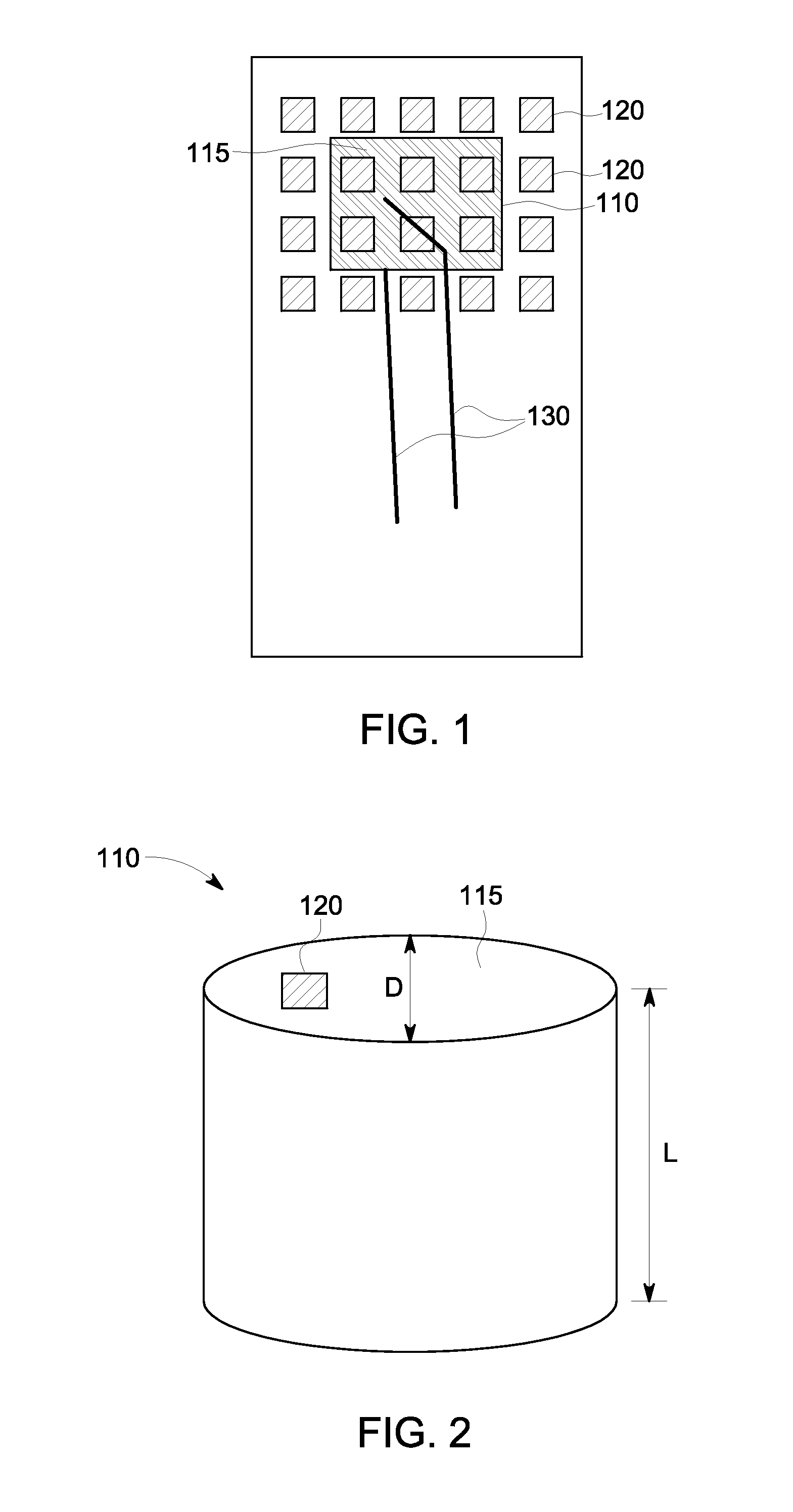
[0013]FIG. 1 depicts a thermistor 110 according to an embodiment of the invention. In the exemplary embodiment shown in FIG. 1, the thermistor 110 includes a ceramic block formed as a rectangular cube, for example, with the (rectangular) top (as illustrated in the figure, not necessarily always on top with respect to gravity) surface visible. The thermistor 110 has a contact 115 surface applied to one or both of the opposite ends of the exemplary cube shape, one shown and one not shown (at a bottom surface of the cube-shaped thermistor 110) in FIG. 1. The contact 115 is of a conductive material that may be a metal and in some embodiments may be...


PUM

PropertyMeasurementUnit
surface areaaaaaaaaaaa
radiusaaaaaaaaaa
diameteraaaaaaaaaa

Abstract

A method of constructing a thermistor includes forming a semiconductor ceramic substrate. The method also includes coating a surface of the substrate with contact material and applying a solder mask on the contact material. The applying includes applying the solder mask to one or more portions of the contact material to leave an exposed area without the solder mask and a masked area with the solder mask. The method includes trimming the contact material at the masked area to adjust a resistance of the thermistor.

Description

BACKGROUND OF THE INVENTION[0001]The present invention relates to resistance trimming for thermistors and, more particularly, to automated resistance trimming after soldering.[0002]A thermistor is a temperature-sensing element by virtue of the fact that it is a type of electrical component whose resistance varies with temperature. The thermistor comprises a semiconductor ceramic which is pressed, cast, molded, or otherwise formed into a substrate in the shape of a block or cylinder, for example. The thermistor may be formed of a polymer, as well. Contacts are added to the substrate. The thermistor undergoes thermal changes during the addition of the contacts. Thus, an aging process is typically undertaken to allow the resistance characteristic of the thermistor to stabilize. Leads are soldered to the contact surface, generally resulting in the solder covering the entire contact surface. While the process does not cause any problem with respect to physical connection of the leads to ...

Claims


Application Information

Patent Timeline
Patent Type & Authority Applications(United States)
IPC IPC(8): H01C17/242H01C7/00
CPCH01C7/008H01C17/003H01C17/065H01C17/242
Inventor GEER, DAVID JOHN
Owner AMPHENOL THERMOMETRICS
Why Eureka
Try Eureka