
Control system and control method for hybrid vehicle

a control system and hybrid technology, applied in vehicle position/course/altitude control, process and machine control, instruments, etc., can solve the problems of deterioration of drivability, difficulty in matching an increase in regeneration amount, and need to increase clutch hydraulic pressure, so as to reduce drivability and fuel economy.

Inactive Publication Date: 2014-05-29
TOYOTA JIDOSHA KK
View PDF0 Cites 20 Cited by
  • Summary
  • Abstract
  • Description
  • Claims
  • Application Information

AI Technical Summary

Benefits of technology

This patent describes a control device for hybrid vehicles that helps to improve fuel economy and driving performance when there is a request to increase the amount of regeneration during downshifts. The device is able to quickly increase the amount of regeneration when the battery has low charge, and then delay the increase until after the downshift is complete when the battery has higher charge. This helps to prevent any deterioration of driving performance and makes the vehicle smoother and more efficient. Overall, the control device helps to maintain optimal performance under various driving conditions.

Problems solved by technology

If the amount of regeneration is increased during such a downshift, it is required to increase the torque capacity of the transmission with an increase in the amount of regeneration, with the result that it is required to increase clutch hydraulic pressure during shifting.
However, the response of the clutch hydraulic pressure and the response of the electric motor generally differ from each other, so it is difficult to match an increase in the amount of regeneration with the timing of an increase in the clutch hydraulic pressure, and there may occur, for example, steep engagement, or the like, of a clutch, and drivability may deteriorate.
However, in control described in JP 2011-199959 A, an increase in the amount of regeneration is suppressed until completion of the shift, so the amount of electric power generated through regeneration may reduce as compared to that when the amount of regeneration is increased, and it may be difficult to improve fuel economy.

Method used


Image

  • Control system and control method for hybrid vehicle
  • Control system and control method for hybrid vehicle
  • Control system and control method for hybrid vehicle

Examples


Embodiment Construction

[0018]Here, preferably, regenerative coast traveling corresponds to a drive mode in which regeneration is carried out by an electric motor during coast traveling. Coast traveling includes coasting and decelerating.

[0019]Hereinafter, an embodiment of the invention will be described in detail with reference to the accompanying drawings. In the following embodiment, the drawings are simplified or deformed as needed, and the scale ratio, shapes, and the like, of portions are not always accurately drawn.

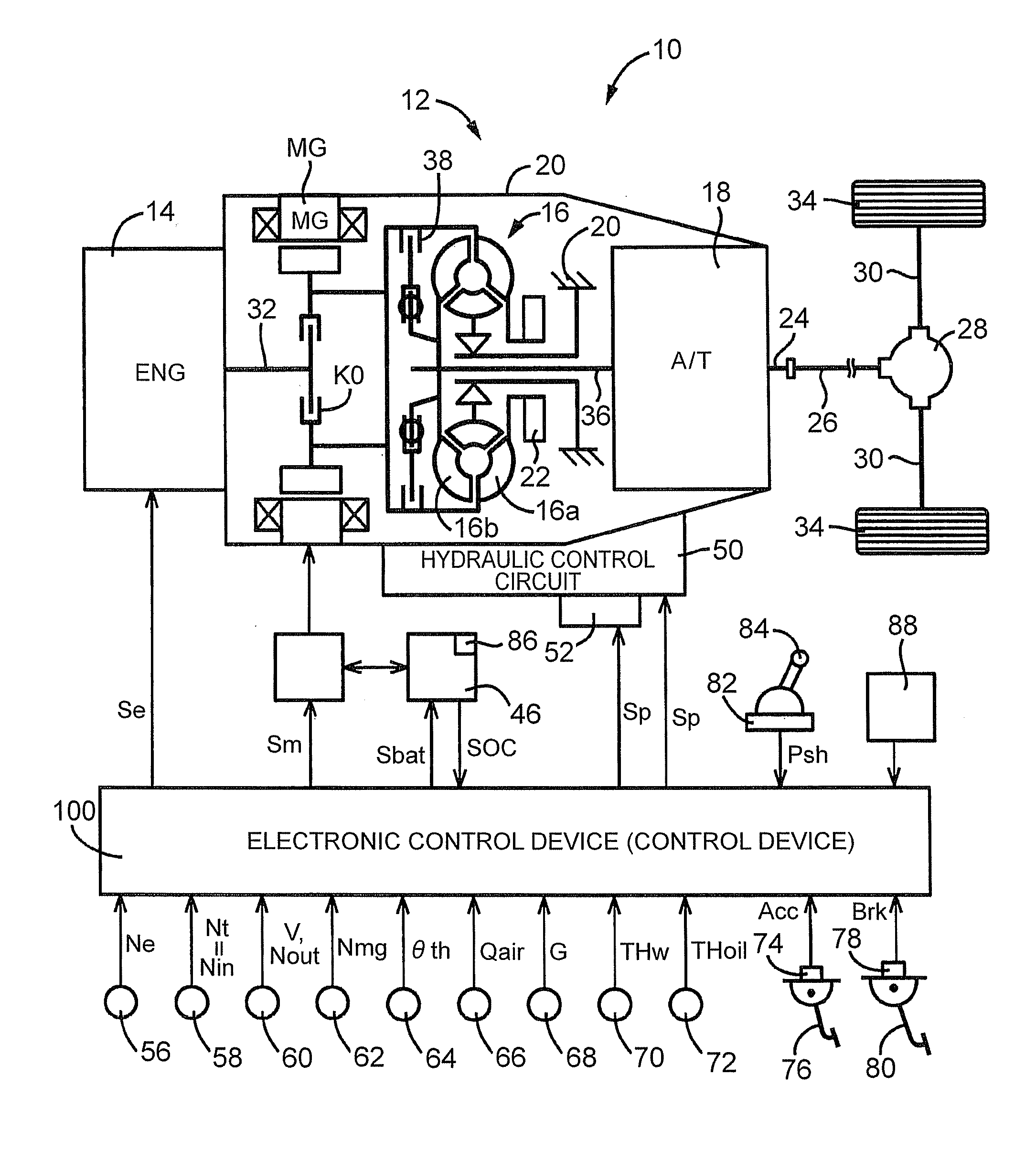
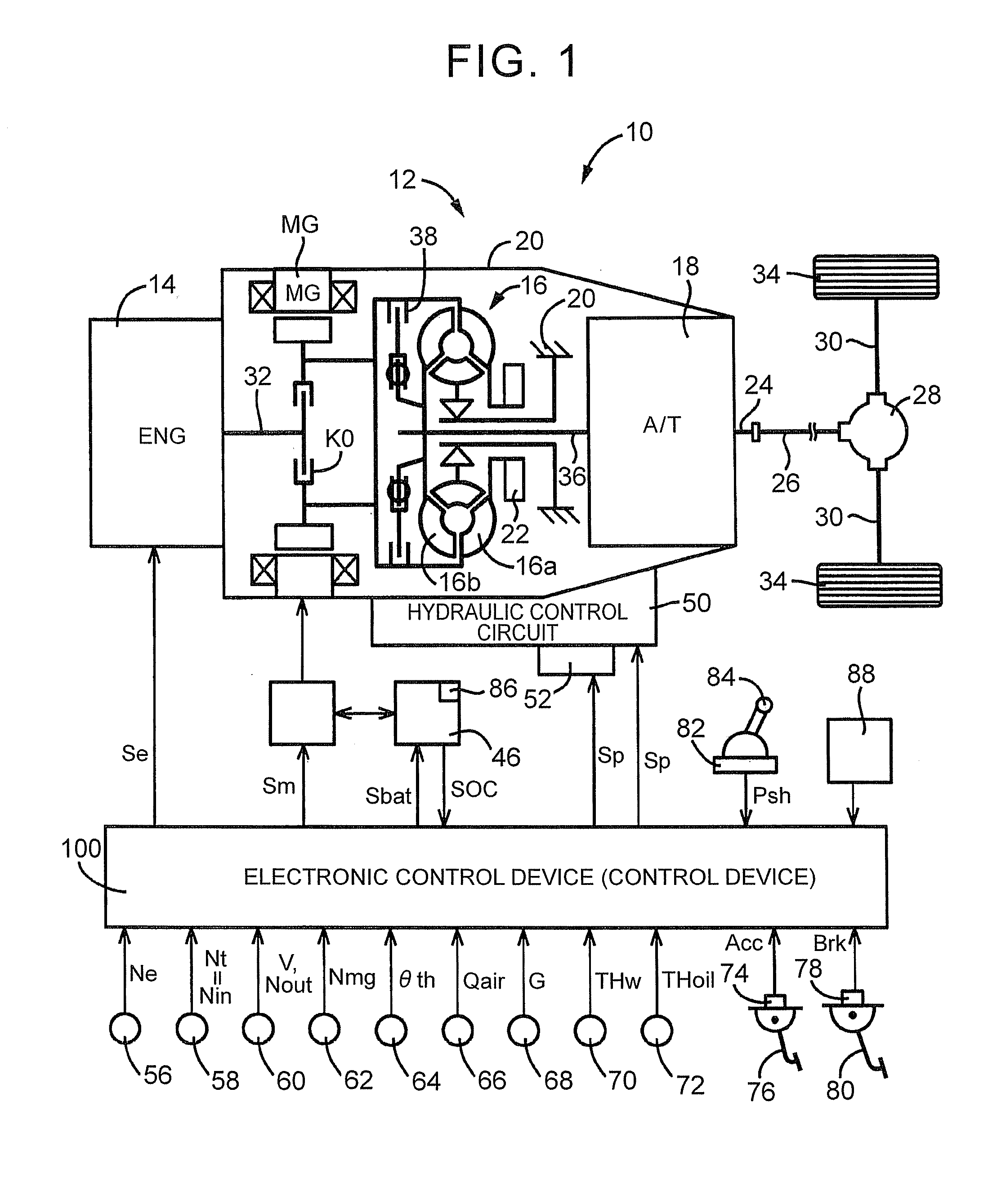
[0020]FIG. 1 is a view that illustrates the schematic configuration of a power transmission path from an engine 14 and an electric motor MG to drive wheels 34, which constitute a hybrid vehicle 10 (hereinafter, referred to as vehicle 10). FIG. 1 is a view that illustrates a relevant portion of a control system provided in the vehicle 10 for output control over the engine 14 that functions as a driving force source, shift control over an automatic transmission 18, drive control over the el...


PUM


Abstract

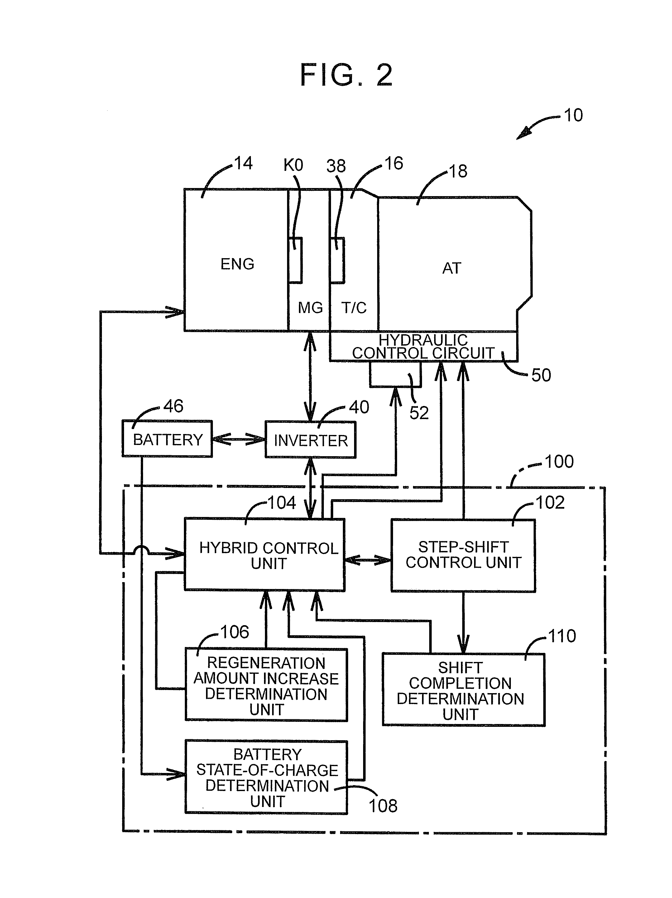
A control system for a hybrid vehicle includes a controller. When a downshift of a transmission and an increase in an amount of regeneration are carried out during regenerative coast traveling in which regeneration is carried out by an electric motor, and when a state of charge of a battery is lower than a predetermined value, the controller increases the amount of regeneration before completion of the downshift. When the state of charge of the battery is higher than or equal to the predetermined value, the controller increases the amount of regeneration after completion of the downshift.

Description

INCORPORATION BY REFERENCE[0001]The disclosure of Japanese Patent Application No. 2012-256980 filed on Nov. 24, 2012 including the specification, drawings and abstract is incorporated herein by reference in its entirety.BACKGROUND OF THE INVENTION[0002]1. Field of the Invention[0003]The invention relates to a control system and control method for a hybrid vehicle and, more particularly, to shift control during regenerative coast traveling.[0004]2. Description of Related Art[0005]There is widely known a hybrid vehicle that includes an engine and an electric motor, each of which functions as a driving force source, and a transmission provided in a power transmission path between drive wheels and both the engine and the electric motor. The thus configured hybrid vehicle is able to travel by appropriately switching into an engine drive mode or a motor drive mode. In the engine drive mode, the hybrid vehicle travels mainly using the driving force of the engine. In the motor drive mode, t...

Claims


Application Information

Patent Timeline
IPC IPC(8): B60W20/00B60L50/16
CPCB60W10/06B60W10/08B60W10/10B60W20/00B60W2510/244Y10S903/903B60K6/48B60W10/11B60W10/26B60W30/18127B60W30/186B60W30/19B60W2710/083F16H63/50Y02T10/62
Inventor SATO, SHUNSUGIMURA, TOSHIOKUWAHARA, SEIJITSUTSUMI, TAKAHIKOMINAMIKAWA, KOKI
Owner TOYOTA JIDOSHA KK
Learn More