
Method of configuring large signal model of active device

a large signal model and active device technology, applied in the field of large signal model of active devices, can solve the problems of large error, inability to prepare a model directly for the large active device, and inability to accurately represent the active device model

Inactive Publication Date: 2014-05-29
ELECTRONICS & TELECOMM RES INST
View PDF8 Cites 2 Cited by
  • Summary
  • Abstract
  • Description
  • Claims
  • Application Information

AI Technical Summary

Benefits of technology

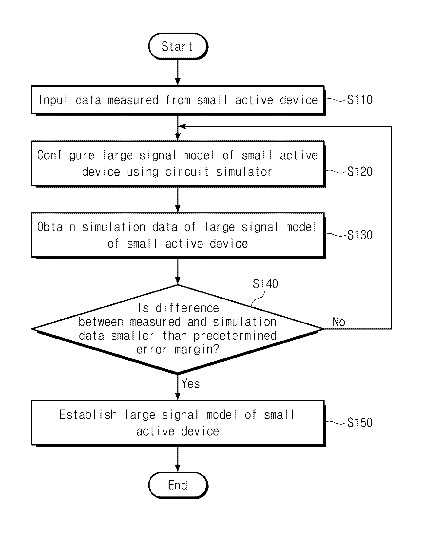
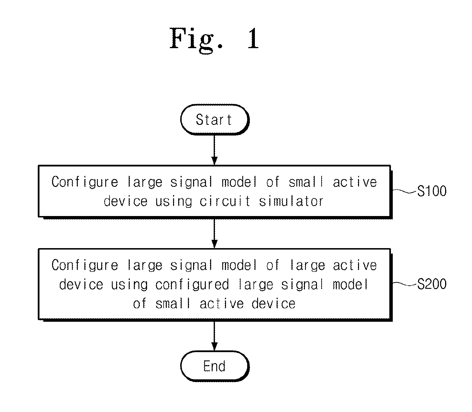
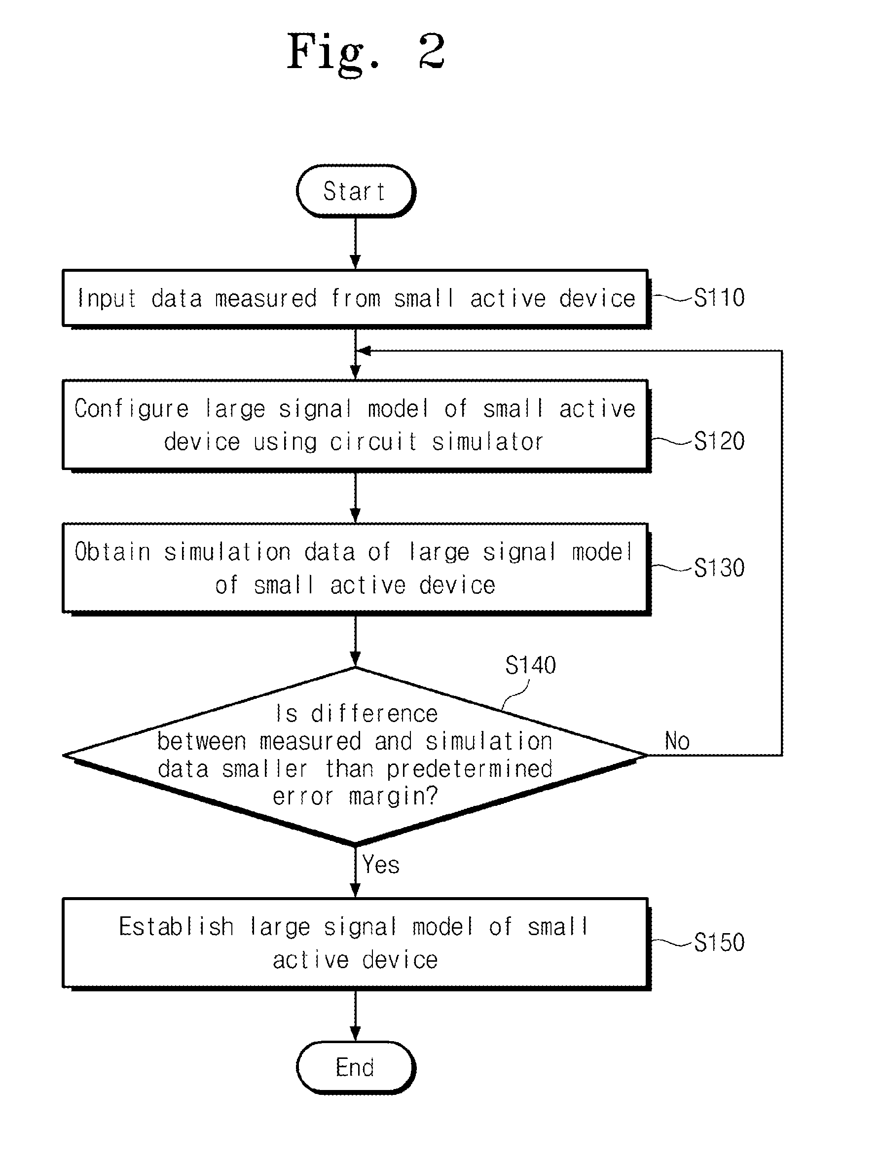
The patent allows for the creation of a large signal model of a small active device, which can be measured over the whole range of characteristics. This model can then be used to create a larger model that can be measured over a smaller range of characteristics. The method involves using a circuit simulator to process and simulate the characteristics of the small device, and then comparing the measured and calculated data to establish the correct model. The technical effect is the ability to accurately measure the characteristics of small active devices using a large signal model that can be measured over a wide range of characteristics.

Problems solved by technology

Further, accuracy of the active device model may affect time taken to design and fabricate an integrated circuit.
However, as the result of limitations related to a measurement range of a measuring instrument or a measurement environment, some (e.g., a large active device) of the active devices may be measured over a partial range.
Accordingly, it is hard to prepare a model for the large active device directly.
Alternatively, a scaling-allowed model has been developed, but it suffers from large error.
However, there is a limitation in measuring the RF characteristic of an active device whose size is larger than a specific size, due to limitation related to measuring instruments.
This means that there is a difficulty in modeling a large active device.

Method used


Image

  • Method of configuring large signal model of active device
  • Method of configuring large signal model of active device
  • Method of configuring large signal model of active device

Examples


Embodiment Construction

[0014]Example embodiments of the inventive concepts will now be described more fully with reference to the accompanying drawings, in which example embodiments are shown. Example embodiments of the inventive concepts may, however, be embodied in many different forms and should not be construed as being limited to the embodiments set forth herein; rather, these embodiments are provided so that this disclosure will be thorough and complete, and will fully convey the concept of example embodiments to those of ordinary skill in the art. In the drawings, the thicknesses of layers and regions are exaggerated for clarity. Like reference numerals in the drawings denote like elements, and thus their description will be omitted.

[0015]It will be understood that when an element is referred to as being “connected” or “coupled” to another element, it can be directly connected or coupled to the other element or intervening elements may be present. In contrast, when an element is referred to as bein...


PUM


Abstract

Provided is a method of configuring a large signal model of an active device. The method may include configuring a large signal model of a first active device, preparing a first measured value on a first characteristic of a second active device, the second active device being larger than the first active device, processing the large signal model of the first active device using a circuit simulator to configure a large signal model of the second active device, simulating the large signal model of the second active device to obtain a calculated value on the first characteristic, comparing the measured and calculated values on the first characteristic to each other, and establishing the large signal model of the second active device, if a difference between the measured and calculated values on the first characteristic may be smaller than a predetermined error margin. Further, if the difference between the measured and calculated values on the first characteristic may be greater than the predetermined error margin, the large signal model of the second active device may be configured by modifying parameters of passive devices.

Description

CROSS-REFERENCE TO RELATED APPLICATIONS[0001]This U.S. non-provisional patent application claims priority under 35 U.S.C. §119 to Korean Patent Application No. 10-2012-0137319, filed on Nov. 29, 2012, in the Korean Intellectual Property Office, the entire contents of which are hereby incorporated by reference.BACKGROUND OF THE INVENTION[0002]Example embodiments of the inventive concept relate to a method of configuring a large signal model of an active device.[0003]A modeling of an active device is essentially required to design an integrated circuit including an active device. If the model for the active device is exact, it may be possible to facilitate design and fabrication of integrated circuits and predict quickly and exactly real characteristics of the integrated circuits. Further, accuracy of the active device model may affect time taken to design and fabricate an integrated circuit.[0004]The active device modeling may be achieved using measurement data. However, as the resul...

Claims


Application Information

Patent Timeline
Patent Type & Authority Applications(United States)
IPC IPC(8): G06F17/50
CPCG06F17/5045G06F30/367H01L2924/0002H01L2924/00G01R31/00G06F17/10G01R27/28H01L23/66H04B17/0085
Inventor CHANG, WOOJIN
Owner ELECTRONICS & TELECOMM RES INST
Learn More