Method and Apparatus for Manufacturing Asymmetrical Roll-Formed Sections

a technology of asymmetrical roll-formed sections and rolling stands, which is applied in the field of rolling, can solve problems such as twisting, bowing, and other defects, and achieve the effect of improving the structure of the rolling stand

Inactive Publication Date: 2014-06-05
DOKTOROV MARK YEFIMOVICH +2
View PDF9 Cites 2 Cited by
  • Summary
  • Abstract
  • Description
  • Claims
  • Application Information

AI Technical Summary

Benefits of technology

[0005]The object of the present invention is to develop a method for the manufacture of asymmetrical angles, channels, and other asymmetrical profiles that includes additional technical steps for centering the workpiece during bending by means of the simultaneous application of opposite moments of the forming forces, and to develop a machine for implementing this method, as well as to improve the structure of the roll stand and the rolls by changing their location and the interaction of the forming elements, as well as introducing a certain relationship between their sizes.

Problems solved by technology

This results in lateral displacement of the workpiece, which can cause twisting, bowing, and other defects, as the workpiece passes through the subsequent roll stands.

Method used


Image

  • Method and Apparatus for Manufacturing Asymmetrical Roll-Formed Sections
  • Method and Apparatus for Manufacturing Asymmetrical Roll-Formed Sections
  • Method and Apparatus for Manufacturing Asymmetrical Roll-Formed Sections

Examples


Embodiment Construction

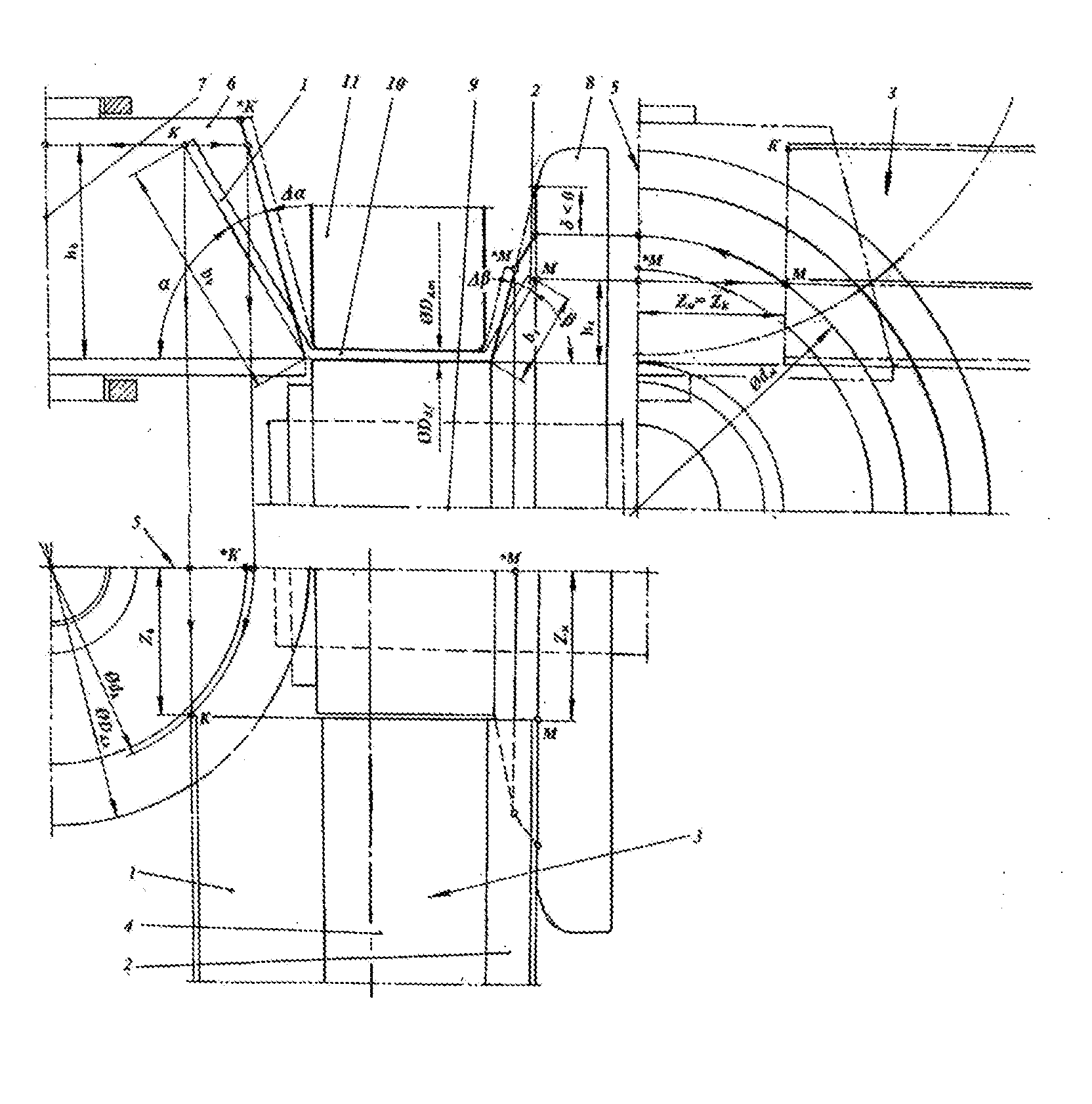
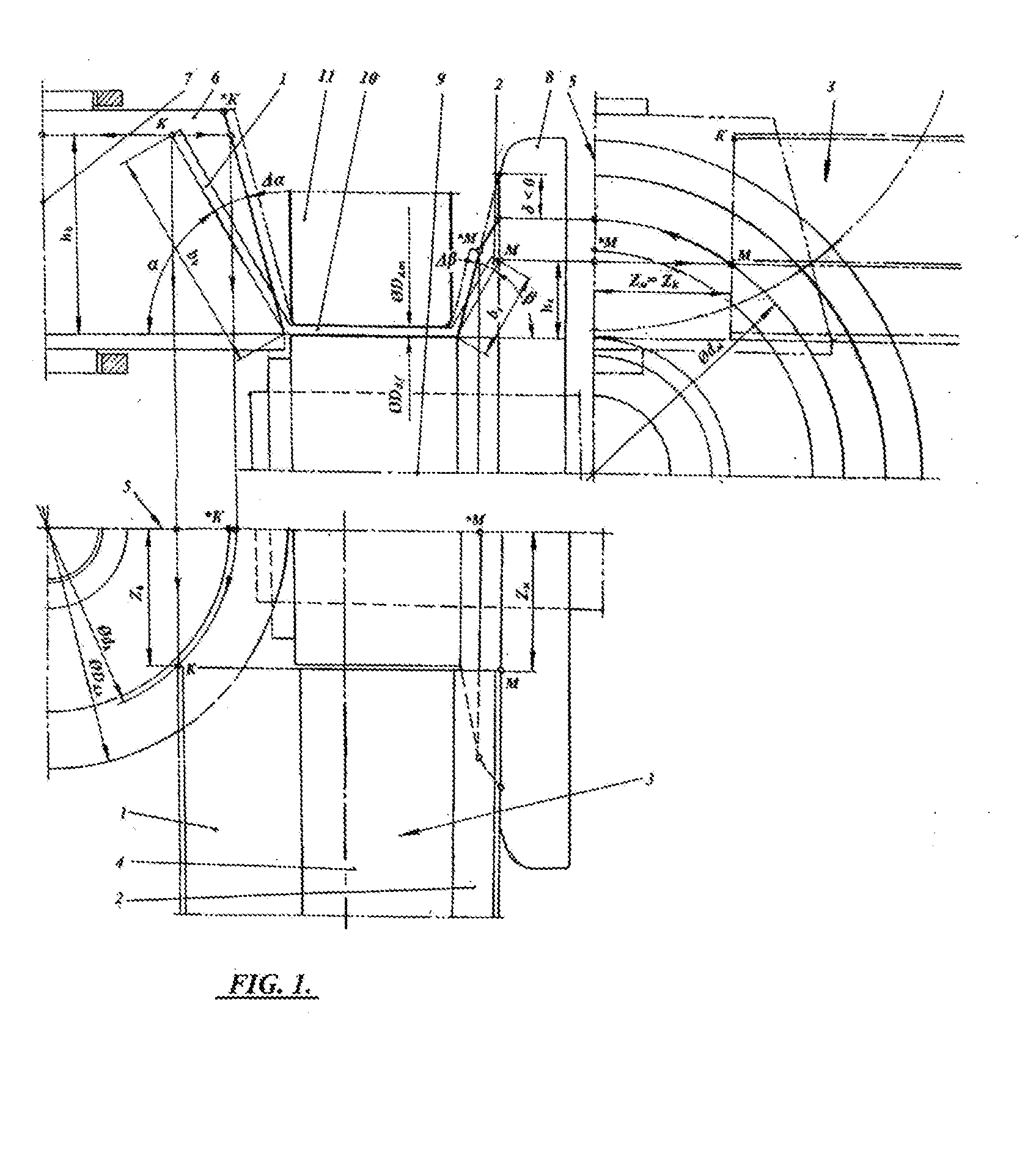
[0022]A method of manufacturing an unequal-flange channel section profile is described below as the preferred embodiment. It is to be understood that the invention is not limited to that particular profile, but is applicable to any other asymmetrical profile. FIG. 1 shows an intermediate stage in roll-forming an unequal-flange channel section profile 3. The longer flange 1 and the shorter flange 2 are bent in relation to the central region 4. The contact between the longer flange 1 and its forming roll is simultaneous with the contact between the shorter flange 2 and its forming roll. Also, the point of initial contact between the longer flange 1 and its forming roll is equidistant from plane 5 to the point of initial contact between the shorter flange 2 and its forming roll. The roll used to bend the longer flange 1 is the vertical female roll 6 (its vertical axis of rotation is 7), and the roll used to bend the shorter flange 2 is the horizontal female roll 8 (its horizontal axis ...


PUM

PropertyMeasurementUnit
widthaaaaaaaaaa
widthaaaaaaaaaa
widthaaaaaaaaaa

Abstract

A roll-forming station for forming asymmetrical sheet metal beams with unequal flanges, where both of the unequal flanges contact the rolls simultaneously and where the diameters of the rolls are such that the bending moments applied to the unequal flanges are identical in magnitude. This prevents lateral displacement of the workpiece during forming.

Description

FIELD OF THE INVENTION[0001]The present invention relates to roll-forming, and more specifically to roll-forming asymmetrical sheet metal sections.BACKGROUND[0002]Roll-forming is a continuous bending operation in which a long flat strip of sheet metal is passed through several sets of rolls mounted on roll stands, each set of rolls bending the strip incrementally further and further until the desired profile is obtained. Typically, the process is used for manufacturing constant-section beams.[0003]While the e are many possible cross-sections that can be manufactured this way, when a cross-section is asymmetrical (such as an unequal-flange U-section), the rolls may not contact the workpiece simultaneously, or the points of contact may not be equidistant from the axial plane of the rolls. This results in lateral displacement of the workpiece, which can cause twisting, bowing, and other defects, as the workpiece passes through the subsequent roll stands.[0004]A need therefore exists fo...

Claims


Application Information

Patent Timeline
Patent Type & Authority Applications(United States)
IPC IPC(8): B21B13/00
CPCB21B13/00B21D5/08
Inventor DOKTOROV, MARK YEFIMOVICHDOKTOROV-BOYKO, NATALIYA LEAHDOKTOROV, SEMION
Owner DOKTOROV MARK YEFIMOVICH
Why Eureka
Try Eureka