Cycloid drive epicycloid planet gear cam

a technology of epicycloid planets and gear cams, applied in the field of cycloid drives, can solve the problems of high start-up force, high cost, and high manufacturing precision of threaded screws and nuts, and achieve the effects of reducing production costs, fine, accurate and repeatable output movements per input rotation, and reducing manufacturing costs

Inactive Publication Date: 2014-06-05
MCGRATH PATRICK JAMES
View PDF3 Cites 19 Cited by
  • Summary
  • Abstract
  • Description
  • Claims
  • Application Information

AI Technical Summary

Benefits of technology

[0021]As a result, the epicycloid planet gear cam of the present invention simply and effectively converts rotational movement of the driveshaft into linear movement of the output device.
[0022]Additionally, the epicycloid planet gear cam of the present invention is more efficient and adaptable than conventional leadscrews. The efficiency benefit provided by the cooperation of the epicycloid planet gear, the internal stationary ring gear, and the driveshaft eccentric is superior to conventional leadscrews. Also, the flexibility in design of the cam track of the present invention allows for advanced control of movement of the output device that can not be matched by conventional leadscrews without costly electronic control systems. In addition, very fine, accurate and repeatable output movements per input rotation can be easily achieved with a varying height epicycloid planet gear ca...

Problems solved by technology

One disadvantage is that the threaded screw and nut require high manufacturing precision and, so, are relatively high cost.
Another disadvantage is that very fine movements per rotation are difficult to achieve because of the difficulty of machining very fine pitch threads.
Also, conventional leadscrews must be well lubricated throughout their service life as high stiction (static friction) will require high start up forces after long periods of immobility if the leadscrew's lubrication layer isn't maintained.
Furthermore, applying force on the load attached to the nut can cause the conventional leadscrew to rotate or back drive.
In many...

Method used


Image

  • Cycloid drive epicycloid planet gear cam
  • Cycloid drive epicycloid planet gear cam
  • Cycloid drive epicycloid planet gear cam

Examples


Embodiment Construction

[0066]Reference will now be made in detail to the preferred embodiments of the present invention, examples of which are illustrated in the accompanying drawings. Wherever possible, the same reference numbers are used in the drawings and the description to refer to the same or like parts.

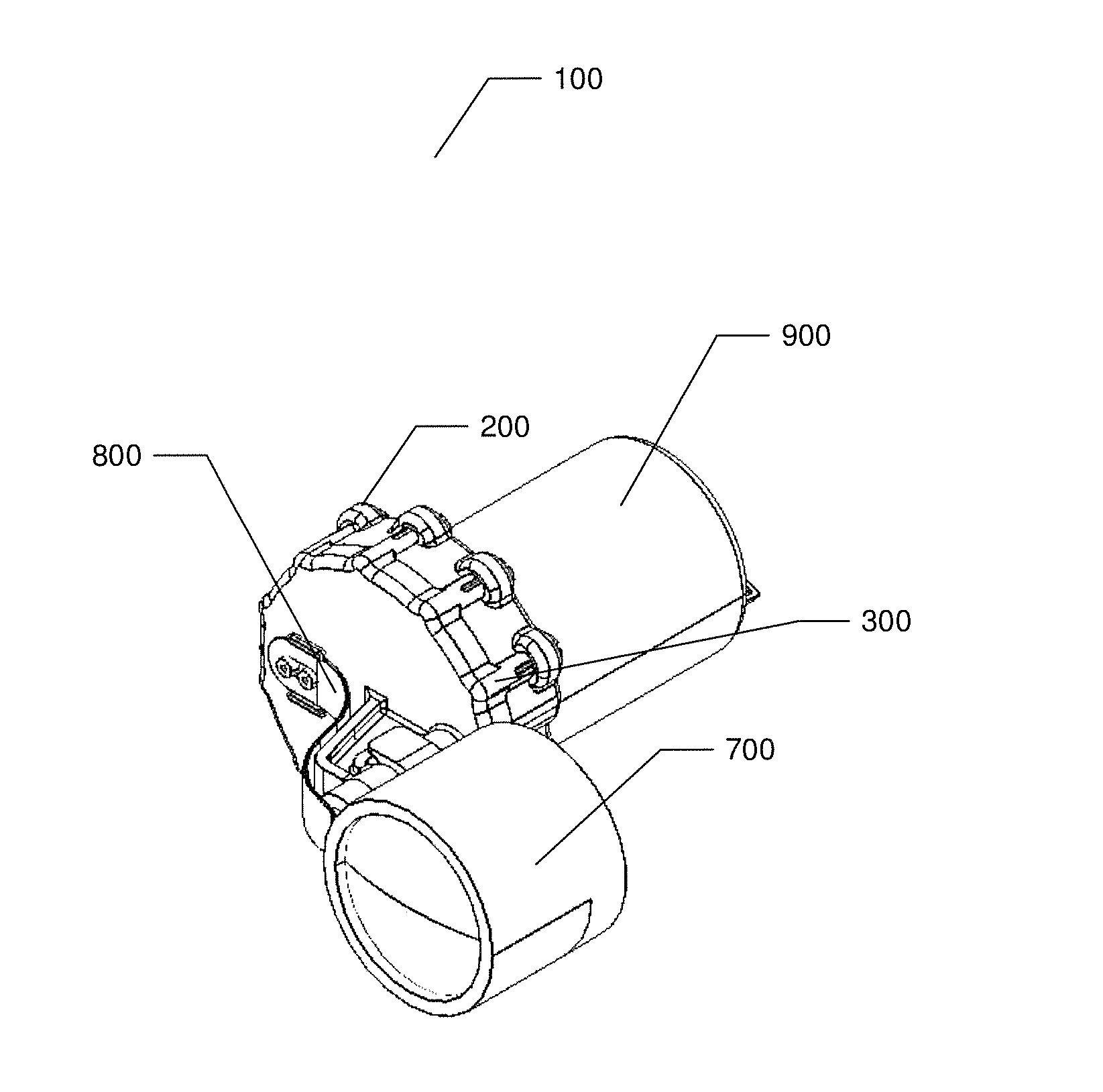
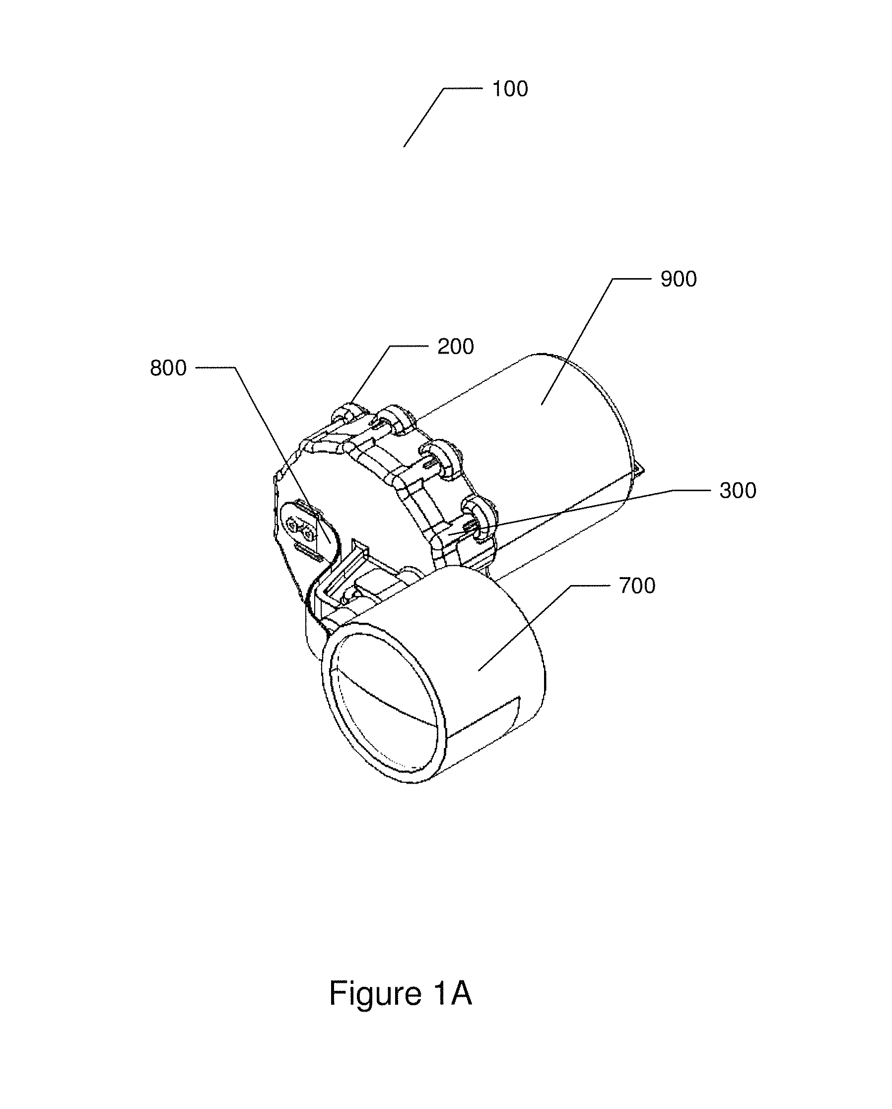
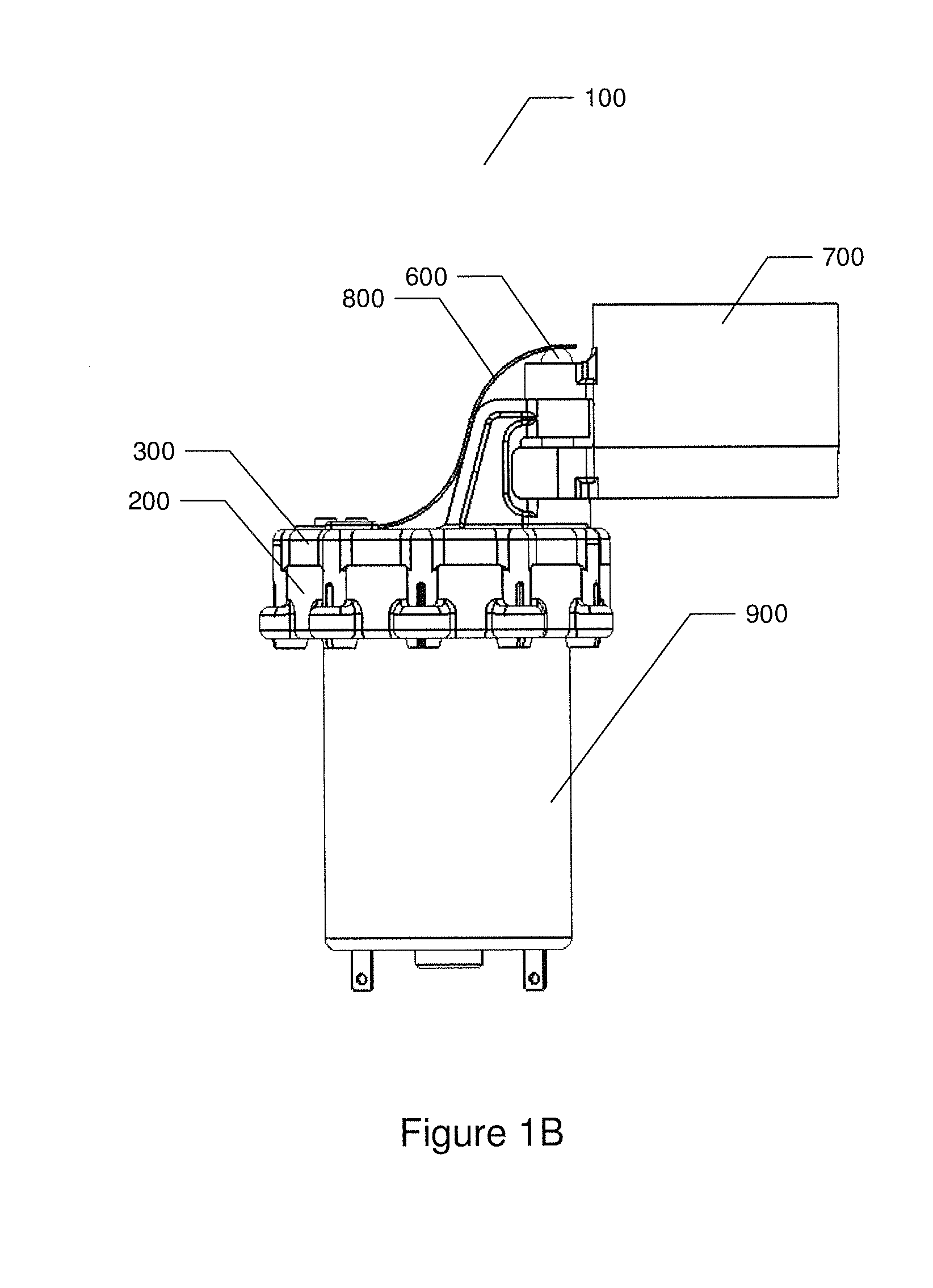
[0067]Refer to FIGS. 1A-1D, which are drawings illustrating an epicycloid planet gear cam according to an embodiment of the present invention.

[0068]As shown in FIGS. 1A-1D the epicycloid planet gear cam 100 of the present invention comprises a stationary housing 200, a housing cap 300, an epicycloid planet gear, a driveshaft eccentric, a cam follower pin 600, a lens carrier 700, a return leaf spring 800, and a direct current (DC) motor 900.

[0069]The stationary housing 200 comprises an internal stationary ring gear. The epicycloid planet gear and the driveshaft eccentric are assembled inside the stationary housing 200 and the housing cap 300 is assembled to the stationary housing 200 thereby encasing ...


PUM


Abstract

An epicycloid planet gear cam that converts rotational movement of a driveshaft into linear movement of an output device is disclosed. An epicycloid planet gear is assembled inside a stationary housing with an internal stationary ring gear. A driveshaft eccentric is connected to a driveshaft. The driveshaft eccentric rotates freely in a mounting hole of the epicycloid planet gear. When the driveshaft rotates, the driveshaft eccentric engages the epicycloid planet gear against the stationary ring gear and causes the epicycloid planet gear to rotate. A cam follower pin attached to an output device is held against a cam track of the epicycloid planet gear. As the epicycloid planet gear rotates, the raised cam track height or the slotted cam track distance from the center of the epicycloid planet gear causes the cam follower pin to move up, down, in, or out thereby moving the output device.

Description

BACKGROUND OF THE INVENTION[0001]1. Field of the Invention[0002]The present invention relates to cycloid drives. More specifically, the present invention discloses an epicycloid planet gear mounted raised cam track or slotted cam track for converting rotational movement of a driveshaft into linear movement of an output object while utilizing the advantageous speed reduction and torque magnification properties of a cycloid drive.[0003]2. Description of the Prior Art[0004]A leadscrew is a screw used to translate rotary input motion into linear output motion. The conventional leadscrew is a threaded screw that mates with a nut. As the threaded screw rotates, the nut moves along the screw either forward or backward. A load connected to the nut moves along with the nut.[0005]While useful in various applications the conventional leadscrew has numerous disadvantages.[0006]One disadvantage is that the threaded screw and nut require high manufacturing precision and, so, are relatively high c...

Claims


Application Information

Patent Timeline
IPC IPC(8): F16H25/08
CPCF16H25/14F16H1/32Y10T74/2107
Inventor MCGRATH, PATRICK JAMES
Owner MCGRATH PATRICK JAMES
Why Eureka
Try Eureka