Vertical take-off and landing (VTOL) aerial vehicle and method of operating such a vtol aerial vehicle

a technology of vertical take-off and landing and aerial vehicles, which is applied in the direction of vertical landing/take-off aircraft, rotorcraft, vehicles, etc., can solve the problems of large, unobstructed field of view, etc., and achieve the effect of increasing flow speed, system lift, and increasing thrus

Inactive Publication Date: 2014-06-05
AIRBUS HELICOPTERS DEUT GMBH
View PDF17 Cites 28 Cited by
  • Summary
  • Abstract
  • Description
  • Claims
  • Application Information

AI Technical Summary

Benefits of technology

[0027]Moreover, the torus-type fuselage with a ducted shroud, particularly at the inlet and the outlet of the air flow through the duct, provide further system lift capabilities and selective distribution between the main rotor and the fuselage or shroud, i.e. at the front portion of the inlet to increase flow speed through the outlet of the ducted shroud, said ducted shroud having diffuser characteristics. At least a part of the duct is shaped as a diffuser. Said diffuser part of the duct ends at the bottom of the duct with a maximum cross section at least equal to the cross section of the at least one main rotor. Said diffuser has a minimum cross section defined by a ratio of 0.7 to 0.8 to 1 for minimum cross section / maximum cross section. The diffuser characteristics of the duct add to acceleration of the flow speed through the outlet of the ducted shroud for increased thrust and system lift capabilities of the inventive aerial vehicle.
[0028]According to an important feature of the invention the blade cyclic pitch of the at least one main rotor is utilized to affect the pattern and velocity of any air flow entering the inlet of the fuselage duct to thereby selectively control the lift generated by the fuselage to affect the control of pitch, roll or yaw of the inventive aerial vehicle. In conjunction with the forces and moments of the fuselage induced through velocity of air flow into the aerodynamically shaped torus all required flight controls for the aerial vehicle are provided.
[0029]According to a further important feature of the inventive aerial vehicle the plurality of support struts extending between fuselage and power plant unit assembly house pitch control servos, the drive shaft between the power plant assembly unit housed engine and the main rotor(s) and other equipment, such as stability gyroscopes.
[0030]It is an important advantage of the invention that the shroud enclosing the at least one main rotor within the torus-type fuselage prevents the formation of tip vortices and thus improves efficiency of the at least one main rotor. It is a further important advantage of the invention that the shroud enclosing the at least one main rotor within the torus-type fuselage obstructs the free radiation of sound waves and thus reduces the noise emitted by the inventive aerial vehicle. As the at least one main rotor is protected by the shroud in flight mode, the stability of the inventive aerial vehicle is increased; noise and vibration signatures are reduced. On ground or other contact with the environment, the safety is increased by protecting operating personnel near the inventive aerial vehicle from inadvertently being struck when the at least one main rotor is running
[0031]It is still a further important feature of the invention that the control moments produced by the application of cyclic pitch to the main rotor(s) are amplified by control moments generated by the fuselage as a result of said application of cyclic pitch.
[0032]The at least one main rotor with its plurality of blades with collective and cyclic pitch control is rotated by a drive shaft connected mechanically via the mechanical interconnection system to the propellers attached to each wing of the inventive aerial vehicle. Collective pitch control of the blades of the propellers provides for additional thrust in forward flight along the longitudinal axis of the inventive aerial vehicle, giving in combination with the wings and torus-type fuselage to the inventive aerial vehicle the high-speed capability in flight. The pitch control of the at least one main rotor, the aerodynamically shaping of the shrouded fuselage and the additional introduction of wings and stabilizers allow generation of all required lift, pitch, roll, yaw forces and moments of the inventive aerial vehicle.

Problems solved by technology

The design of the windshields and windows result in a large, unobstructed field-of-view.

Method used


Image

  • Vertical take-off and landing (VTOL) aerial vehicle and method of operating such a vtol aerial vehicle
  • Vertical take-off and landing (VTOL) aerial vehicle and method of operating such a vtol aerial vehicle
  • Vertical take-off and landing (VTOL) aerial vehicle and method of operating such a vtol aerial vehicle

Examples


Embodiment Construction

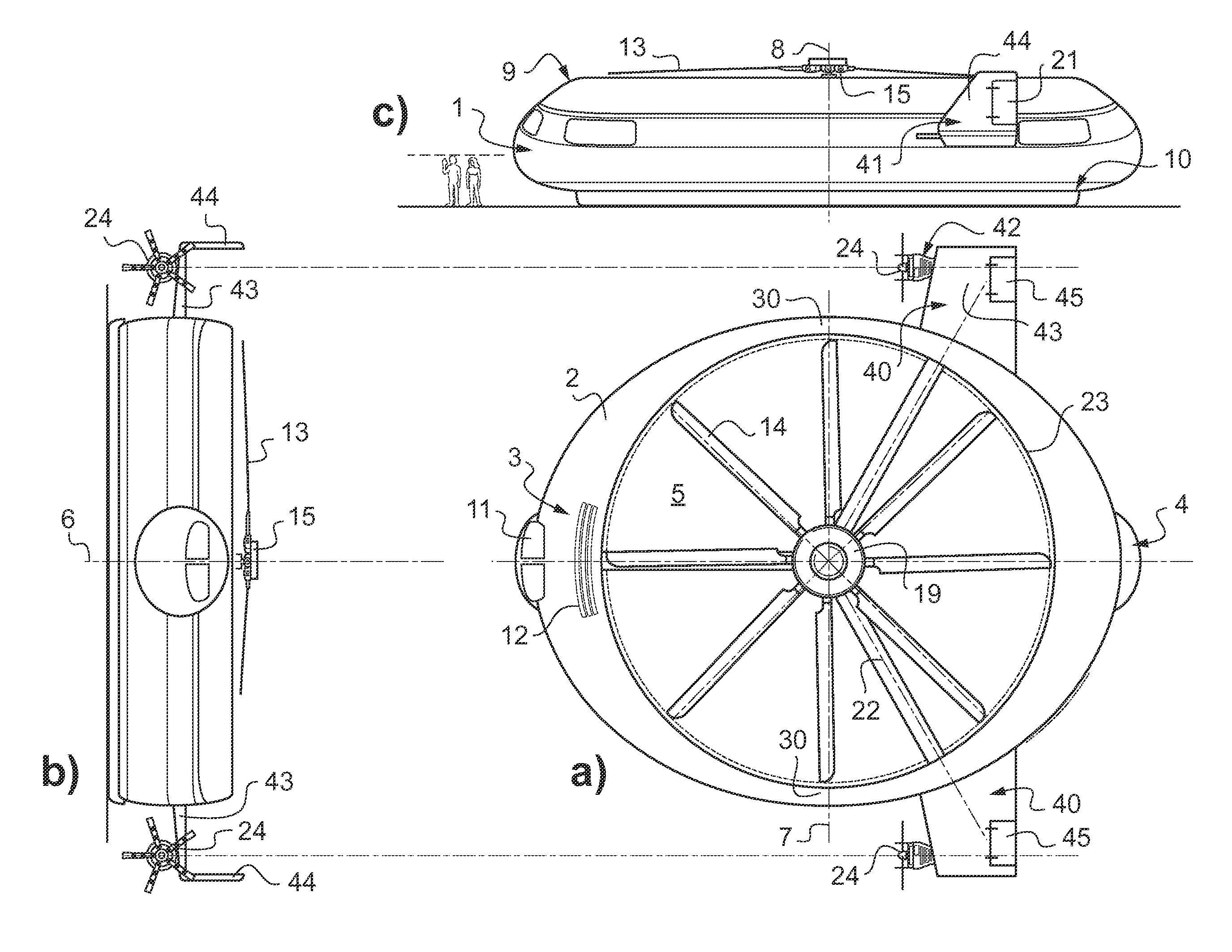
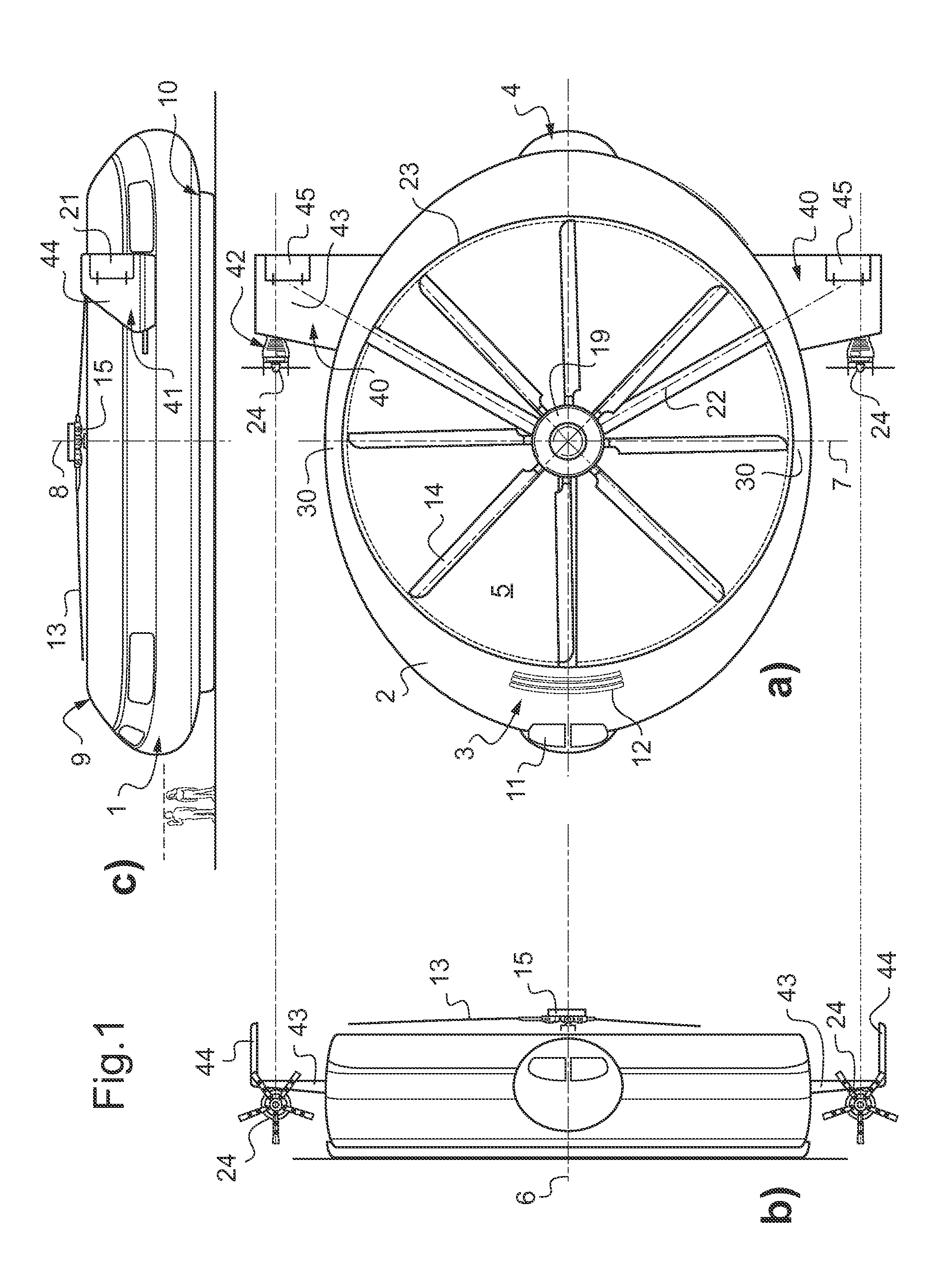
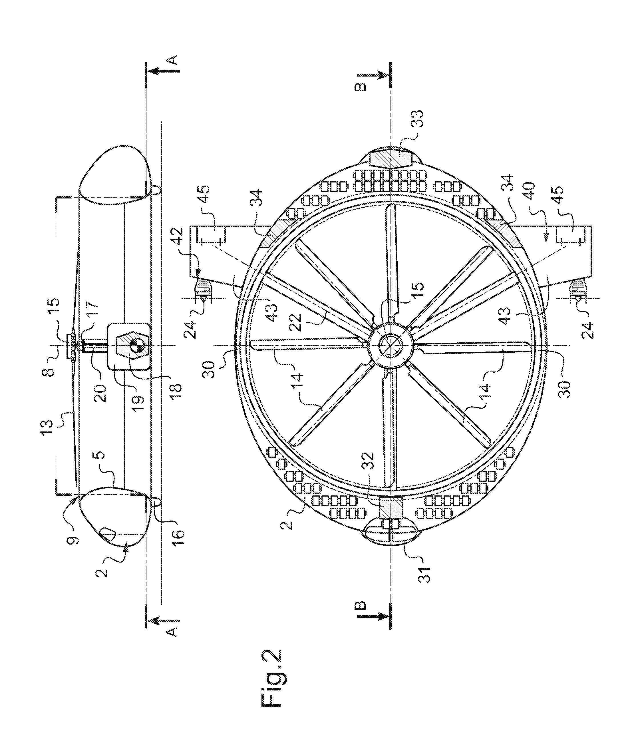
[0043]According to FIG. 1a, 1b, 1c and 2 an aerial vehicle 1 comprises a torus-type or toroidal fuselage 2 with a front portion 3 and a rear portion 4. A generally horizontal plane of the aerial vehicle 1 is defined by a longitudinal 6 and a transversal axis 7 with a central axis 8 perpendicular to said plane. A duct 5 is formed through the torus-type fuselage 2 and extends essentially coaxial to said central axis 8 from a top 9 to a bottom 10 radial inside of the torus-type fuselage 2. The torus-type fuselage 2 is aerodynamically formed like a shroud in order to provide an optimum airflow stream through the duct 5 and around the fuselage 2.

[0044]Inside the torus-type fuselage 2 is a cabin to transport passengers and cargo. The front portion 3 of the fuselage 2 contains the cockpit 31 and galley 32 compartments. Windshields and windows 11 of the cockpit 31 result in a large, unobstructed field-of-view for pilots inside the cockpit 31. A standard entry (not shown) into the cockpit 31...


PUM


Abstract

A Vertical Take-off and Landing (VTOL) aerial vehicle (1, 46), e.g. a rotorcraft with long range and high cruising speed capability. The aerial vehicle (1, 46) has a torus-type fuselage (2) with radial inside a duct (5) and at least one main rotor (13, 26). A pair of lateral wings (40) are attached opposed to each other outside the fuselage (2) and at least one engine (18) drives said at least one main rotor (13, 26) and at least two propulsion means (24) fitted to each of said wings (40). The invention relates as well to a method of operating such a VTOL aerial vehicle (1, 46).

Description

CROSS REFERENCE TO RELATED APPLICATION[0001]This application claims priority to European patent application No. 12 400050.6 filed Nov. 30, 2012, the disclosure of which is incorporated in its entirety by reference herein.BACKGROUND OF THE INVENTION[0002](1) Field of the Invention[0003]The invention relates to a Vertical Take-off and Landing (VTOL) aerial vehicle, e.g., a rotorcraft with long range and high cruising speed capability according to the preamble of claim 1 and to a method of operating such a VTOL aerial vehicle according to the preamble of claim 20.[0004](2) Description of Related Art[0005]There have been numerous attempts to combine the efficiency and performance of fixed-wing aircrafts in forward flight and the advantageous hover and vertical take-off capabilities of helicopters.[0006]The compound helicopters and the convertiplanes are basically the most relevant concepts aiming to overcome the horizontal flight deficiencies of pure helicopters by introducing attribute...

Claims


Application Information

Patent Timeline
Patent Type & Authority Applications(United States)
IPC IPC(8): B64C27/20B64C27/26B64C29/00
CPCB64C29/0025B64C27/22B64C27/26B64C39/001B64C29/00B64C27/20B64C39/06
Inventor CVRLJE, TOMISLAV
Owner AIRBUS HELICOPTERS DEUT GMBH
Why Eureka
Try Eureka