

Touch-panel device
a touch panel and capacitive technology, applied in the field of capacitive touch panel devices, can solve the problems of position detection accuracy degradation of detection electrodes coupled to one another, and achieve the effect of simple configuration and enhanced detection sensitivity
- Summary
- Abstract
- Description
- Claims
- Application Information
AI Technical Summary
Benefits of technology
Problems solved by technology
Method used
Image

Examples
exemplary embodiment 1
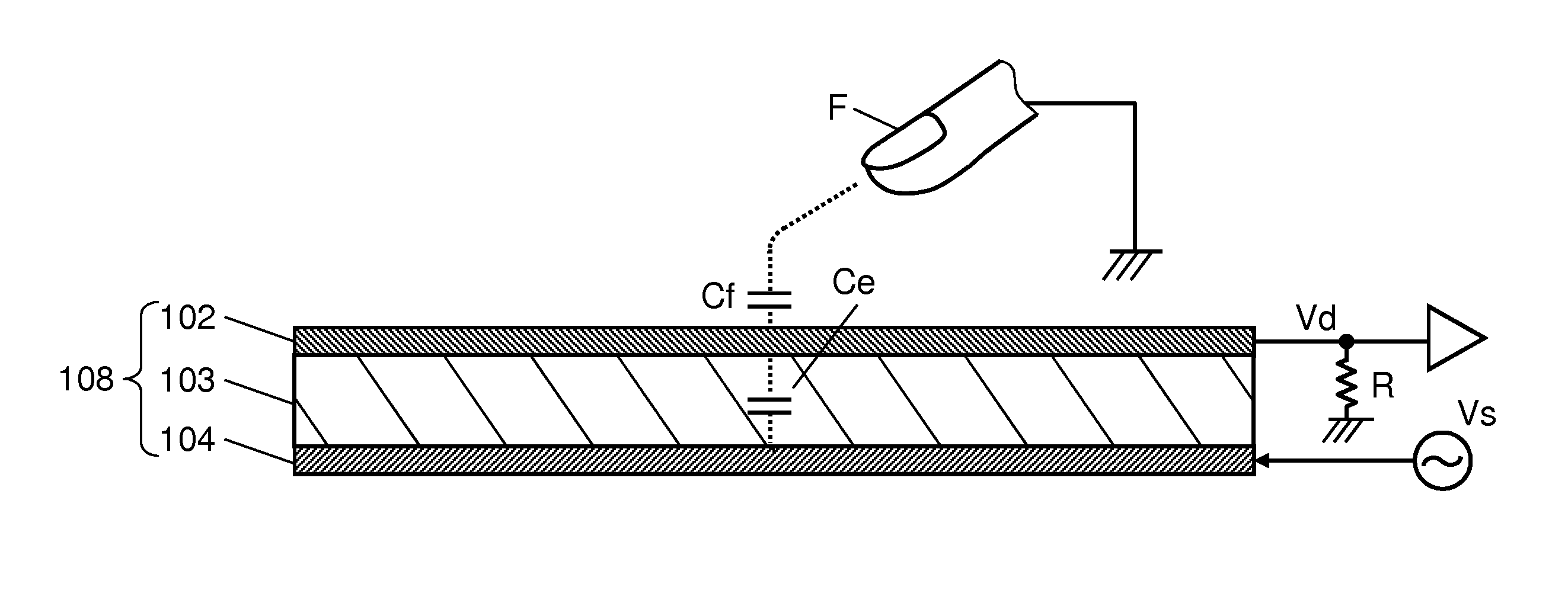
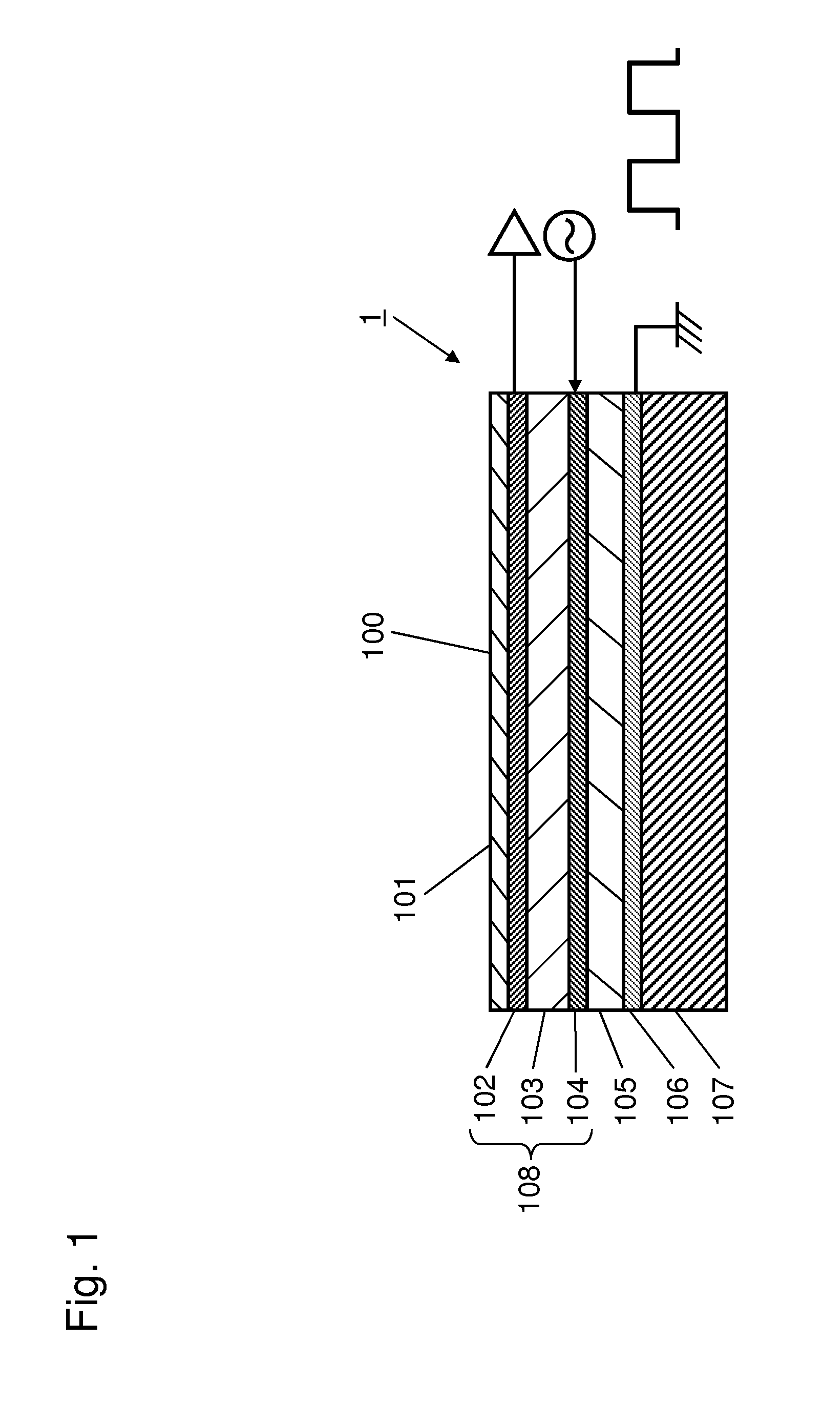
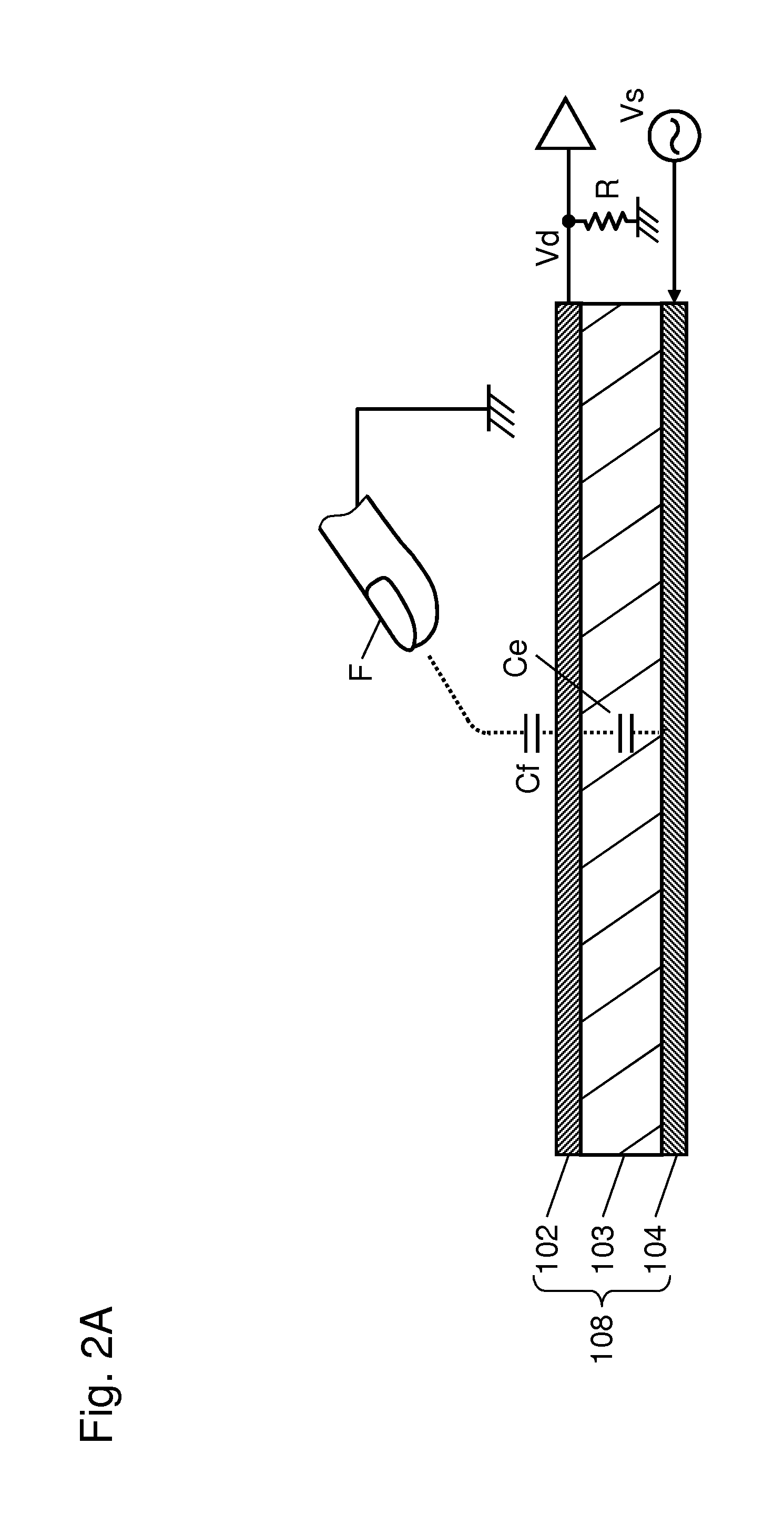
[0054]FIG. 1 is a schematic cross-sectional view of touch panel 100 mounted to touch panel device 1 according to Exemplary Embodiment 1. Touch panel device 1 is a mutual-capacitive type touch panel device. Touch panel device 100 includes liquid crystal display (LCD) 107 functioning as an image display element, electrode layer 108, glass layer 105, shield layer 106, and protection layer 101. Electrode layer 108, glass layer 105, shield layer 106, and protection layer 101 are transparent. LCD 107 and electrode layer 108 faces each other across glass layer 105 and shield layer 106. Protection layer 101 covers (a front surface of) electrode layer 108 which is configured to be touched with an object, such as a finger of an operator, from above. Electrode layer 108 includes drive electrodes 104, glass layer 103 functioning as an insulation layer, and detection electrodes 102 facing drive electrodes 104 across glass layer 103. Drive electrodes 104 and detection electrodes 102 are formed by...
exemplary embodiment 2
[0097]FIG. 9 is a schematic view of touch panel device 2 according to Exemplary Embodiment 2. In FIG. 9, components identical to those of touch panel device 1 according to Embodiment 1 shown in FIG. 1 are denoted by the same reference numerals. Touch panel device 2 according to Embodiment 2 includes touch panel 120 instead of touch panel 100, and further includes divisional electrode switch 127.
[0098]As illustrated in FIG. 9, on touch panel 120, drive electrode Xm (1≦m≦6) is divided into drive electrode Xm1 (1≦m≦6) (third electrode) and drive electrode Xm2 (1≦m≦6) (fourth electrode) at a central part of drive electrode Xm in the Y-axis direction.
[0099]In order to input the AC signal from single AC signal source 110 to drive electrodes Xm1 (1≦m≦6) and drive electrodes Xm2 (1≦m≦6), divisional electrode switch 127 is serially connected to drive electrode switch 112. Divisional electrode switch 127 includes switches TSW7 to TSW12. Control circuit 115 controls divisional electrode switch...
modification 1
[0105]FIG. 10 is a schematic view of Modification 1 of touch panel device 2 according to Embodiment 2. In this modification, AC signals having reverse phases are simultaneously input from one AC signal source 110 to each of divisional drive electrode Xm1 (1≦m≦6) and drive electrode Xm2 (1≦m≦6).
[0106]Inductive element 111 is connected to AC signal source 110. Inductive element 111 is connected to drive electrode switch 124 directly or via phase inverter circuit 125. Drive electrode switch 124 includes six switches TSW13 to TSW18 which are sequentially switched. Each of switches TSW13 to TSW18 includes two switches SW1 and SW2 that are simultaneously turned on and off. Therefore, the AC signals having the reverse phases are simultaneously input from AC signal source 110 to two drive electrode Xm1 (1≦m≦6) and drive electrode Xm2 (1≦m≦6) selected by drive electrode switch 124.
[0107]Thus, this modification does not require divisional electrode switch 127 shown in FIG. 9, hence simplifyin...
PUM
 Abstract
Description
Claims
Application Information