Reduced Size Runner for an Injection Mold System

a technology of injection molding and runners, which is applied in the field of apparatus and methods for injection molding, can solve the problems of excessive shrinkage of molded articles from the mold cavity, undesired high dimensional variation, and large volume of plastic, and achieves the effect of increasing the number of total cavities that can be provided in a given mold, reducing the size of runners, and increasing the number of total cavities

Active Publication Date: 2014-06-05
IMFLUX INC
View PDF3 Cites 14 Cited by
  • Summary
  • Abstract
  • Description
  • Claims
  • Application Information

AI Technical Summary

Benefits of technology

[0019]Decreasing the size of the runners has several benefits. In the case of cold runners, decreasing the runner size advantageously increases options regarding the mold cavity spacing because the cavities may be spaced more closely to one another. Potentially, so much space between cavities can be saved in an overall mold such that the number of total cavities that can be provided in a given mold can be increased. Another advantage to a decreasing runner size in a cold runner system is that it reduces the energy needed to introduce molten polymer through the runner system and ultimately to the mold cavities.
[0020]An additional benefit of smaller feed channels or runners in a cold runner system as compared to conventional injection molding systems is that because the cold runner is ejected or otherwise removed at the end of a molding cycle, and reground for use in subsequent molding cycles, reducing the size of the runners reduces the size of those cold runners that need to be ejected or removed at the end of a molding cycle. By reducing the size of the runners, and thereby reducing the amount of material that needs to be reground, the integrity and quality of the resulting molded articles is increased, because the percentage of regrind in any given injection molding cycle is reduced.
[0021]For a hot runner system, a benefit of a reduced-sized runner is that there is less of a pressure drop from branch to branch of the runners (i.e., from runners closest to the nozzle to the runners closest to the mold cavities), permitting the injection molding system to maintain constant pressure and make more consistent parts. A reduced hot runner size translates to reduced molten polymer in the runner system, thereby reducing the polymer residence time, and shortening the duration of exposure to heat (minimizing polymer degradation). With less polymer material contained in the hot runner, less material would need to be purged from the system when changing the color of a polymer or changing from one polymer material to another polymer material, thereby reducing changeover time. As with a cold runner system, reduced runner size could provide benefits in spacing, and even overall number, of cavities in a given mold.

Problems solved by technology

If polymeric material within the feeder channel were to freeze prior to the mold cavity being completely packed, the molded article would shrink away from the mold cavity excessively, and the molded article would have poor surface finish quality and undesirably high dimensional variation.
This results in a substantial volume of plastic being required to distribute the polymer to the injection mold cavities.
In the case of a cold runner system, this large volume can extend the cycle times for some parts, increase clamp tonnage (because the larger the volume of the runner system, the higher the volume of polymer material between the machine nozzle and the mold cavities, and the more clamp tonnage that may likely be necessary to mold articles along with the volume of runner material), and this substantial volume of polymer is typically disposed of for each “shot” of polymer injected in to the cavity—since the cold runner is typically discarded as scrap or reground for re-use in subsequent injection molding cycles.
This leads to lost productivity during the material changeover process.

Method used


Image

  • Reduced Size Runner for an Injection Mold System
  • Reduced Size Runner for an Injection Mold System
  • Reduced Size Runner for an Injection Mold System

Examples


example 1

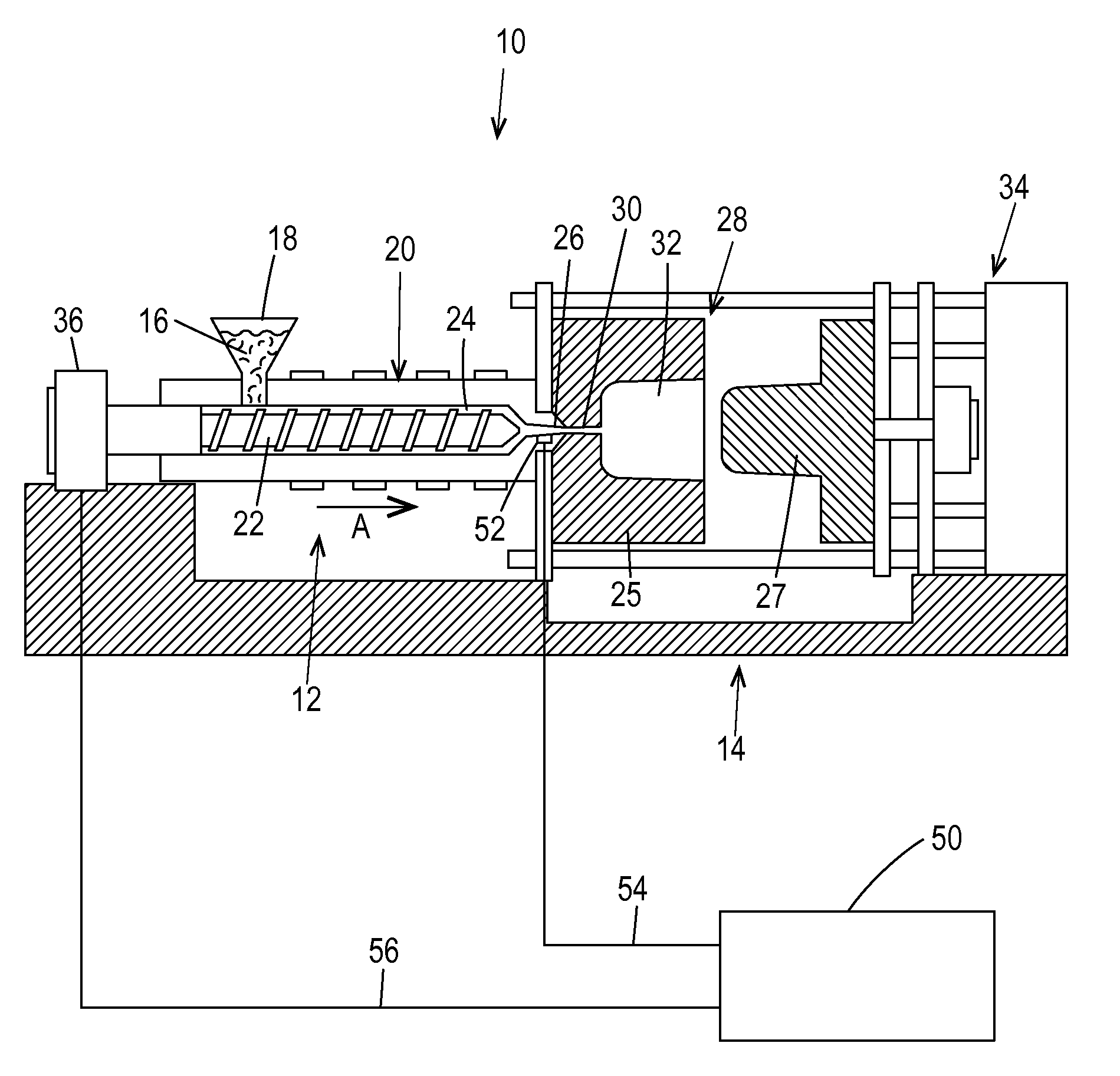
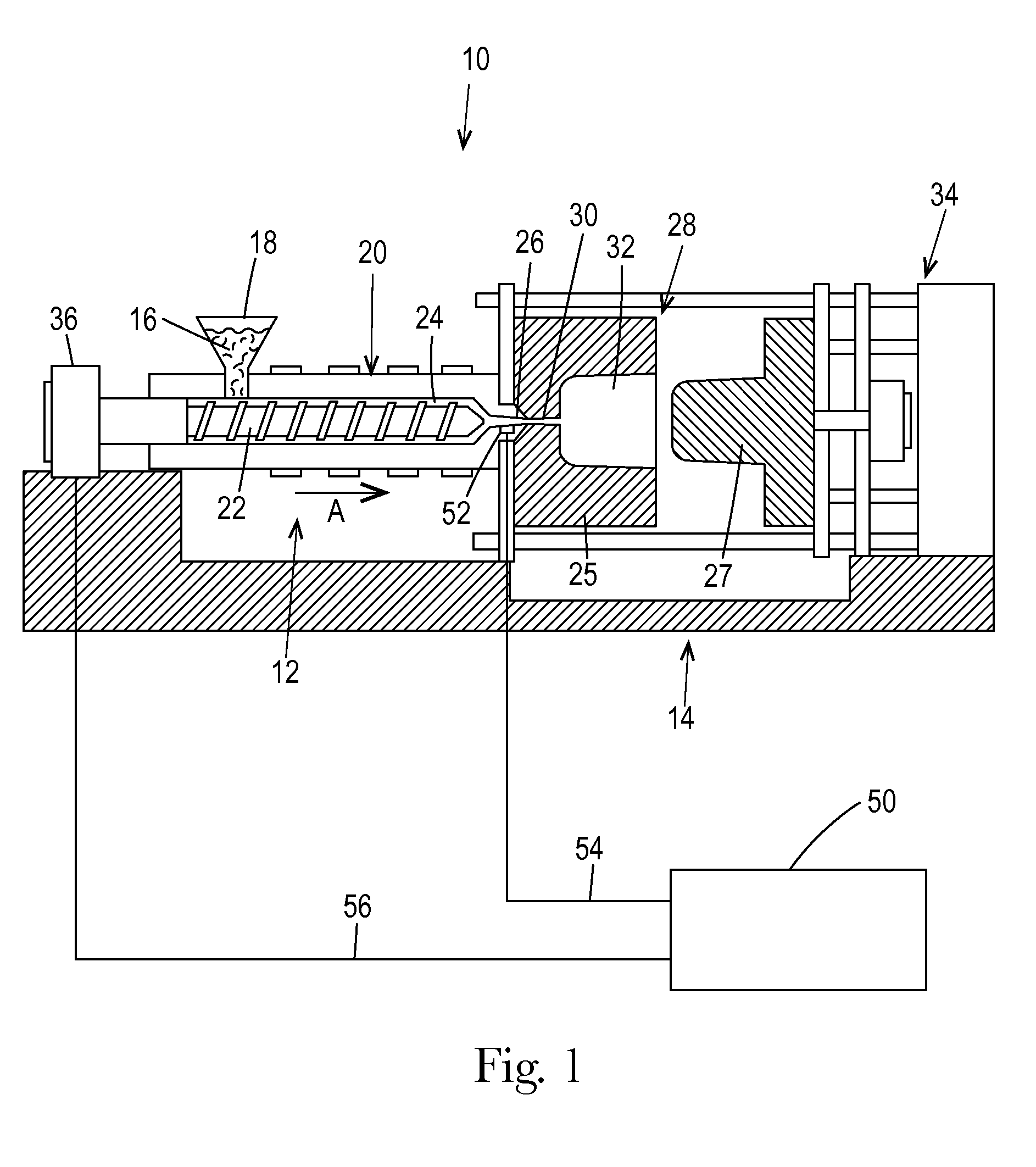
[0057]A test was performed to determine how runner sizes could be designed for use with a substantially constant pressure injection molding process as compared to a conventional variable pressure injection molding process. The test was performed using 20MFI Braskem Polypropelene Homopolymer FT200WV (with no colorant). The test was performed using an Engel 100TL 100-ton hydraulic tiebarless injection molding press. The test was performed with a mold temperature at a constant 65° F. The Melt Temperature was 420° F. For the conventional variable pressure process, a mold viscosity test was performed to establish the injection rate. A set point of 4.5 in / second was used for each run, or volumetrically, 2.65 in3 / sec (43.43cm3 / sec). For the substantially constant pressure process, or “SCPP”, the pressure and time were controlled to achieve the given part weight of 2.51 grams without freezing the gate or runner that would lead to short shots.

[0058]A steel prototyping / experimental mold as de...


PUM

PropertyMeasurementUnit
thicknessaaaaaaaaaa
hydraulic diameteraaaaaaaaaa
diameteraaaaaaaaaa

Abstract

A runner system for a multi-cavity injection molding system, the runner system having runners of reduced size.

Description

FIELD OF THE INVENTION[0001]This disclosure relates generally to apparatuses and methods for injection molding and, more particularly, to apparatuses and methods for producing injection molded parts at substantially constant pressure.BACKGROUND OF THE INVENTION[0002]Injection molding is a technology commonly used for high-volume manufacturing of parts made of meltable material, most commonly of parts made of thermoplastic polymers. During a repetitive injection molding process, a plastic resin, most often in the form of small beads or pellets, is introduced to an injection molding machine that melts the resin beads under heat, pressure, and shear. The now-molten polymer or resin is forcefully injected into a mold cavity having a particular cavity shape. The injected plastic is held under pressure in the mold cavity, cooled, and then removed as a solidified part having a shape that essentially duplicates the cavity shape of the mold. The mold itself may have a single cavity or multip...

Claims


Application Information

Patent Timeline
Patent Type & Authority Applications(United States)
IPC IPC(8): B29C45/27
CPCB29L2031/712B29L2031/3044B29C45/2708B29C45/77B29C2045/2722B29C2945/76006B29C2945/7621B29C2945/76287B29C2945/76936B29C45/2701B29C45/2704B29C45/2725B29C2045/0086
Inventor ALTONEN, GENE MICHAELBREIDENBACH, VINCENT SEANMCCONNELL, KIMBERLY NICHOLELUMPKIN, DANNY DAVIDHUANG, CHOW-CHIBERG, JR., CHARLES JOHN
Owner IMFLUX INC
Why Eureka
Try Eureka