Bone implant

Inactive Publication Date: 2014-06-05
ELOS MEDTECH PINOL AS
View PDF0 Cites 9 Cited by
  • Summary
  • Abstract
  • Description
  • Claims
  • Application Information

AI Technical Summary

Benefits of technology

[0030]Advantageously the first part includes a substantially flat base portion and the external thread extends along the first part to the substantially flat base portion. This ensures that the bone implant is sufficiently cut into the bone and the substantially flat base portion ensures that the bone implant does not extend unnecessarily deep into the bone. Alternatively the first part may include a smooth surface in the form of part of a sphere so that in case the bone implant is inserted too far into the bone, e.g. when mounting in skull bone, there is a reduced risk of damage

Problems solved by technology

Some geometry of previous implants, in all applications mentioned above, has shown to cause compression and/or heating of the bone material thus damaging the bone material; sometimes to such a degree that the bone dies.
The friction, compression and the energy exerted when inserting the bone implant have shown to cause damage to the bone, also with subsequent bone necrosis.
This however leads to other problems such as a

Method used


Image

  • Bone implant
  • Bone implant
  • Bone implant

Examples


Embodiment Construction

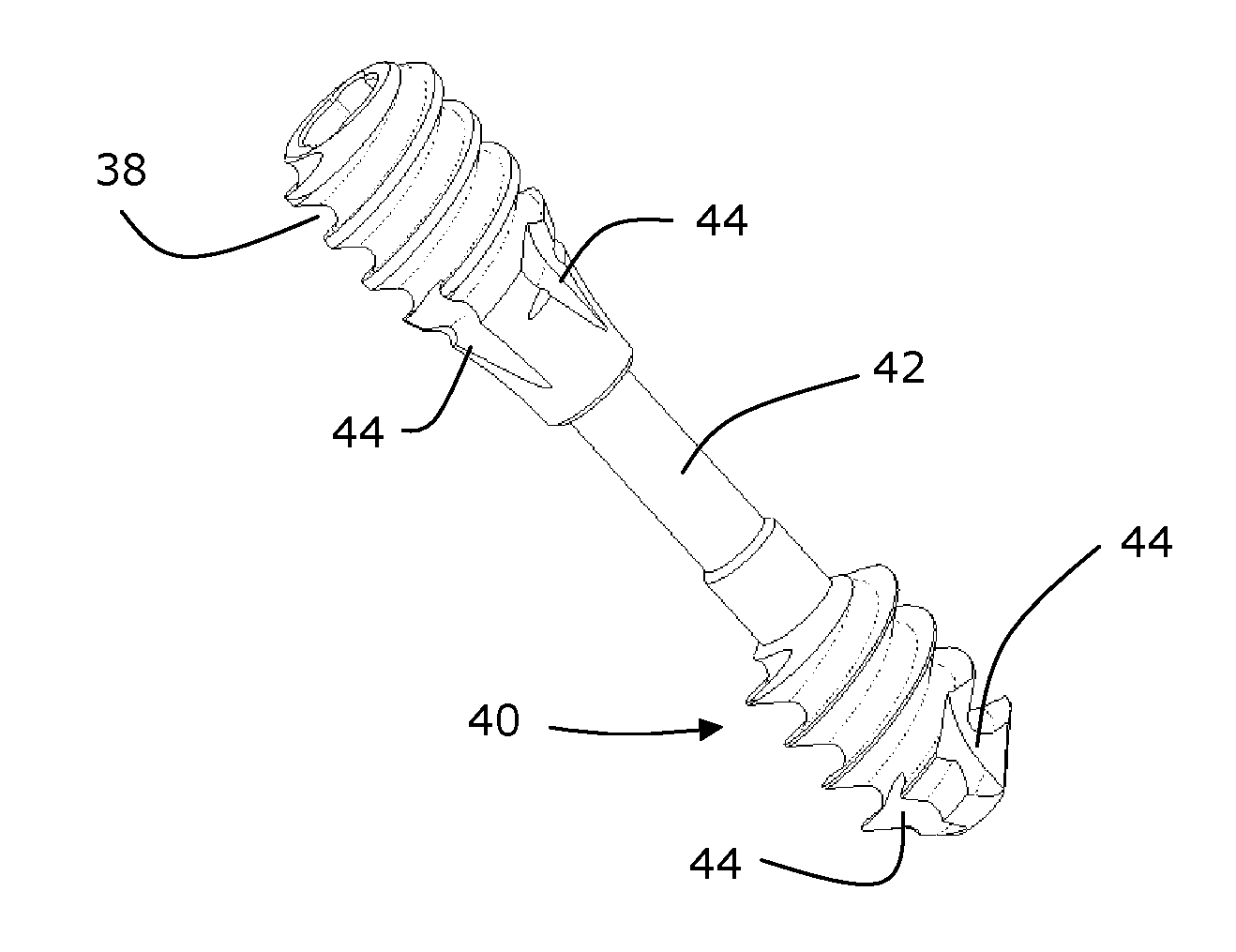
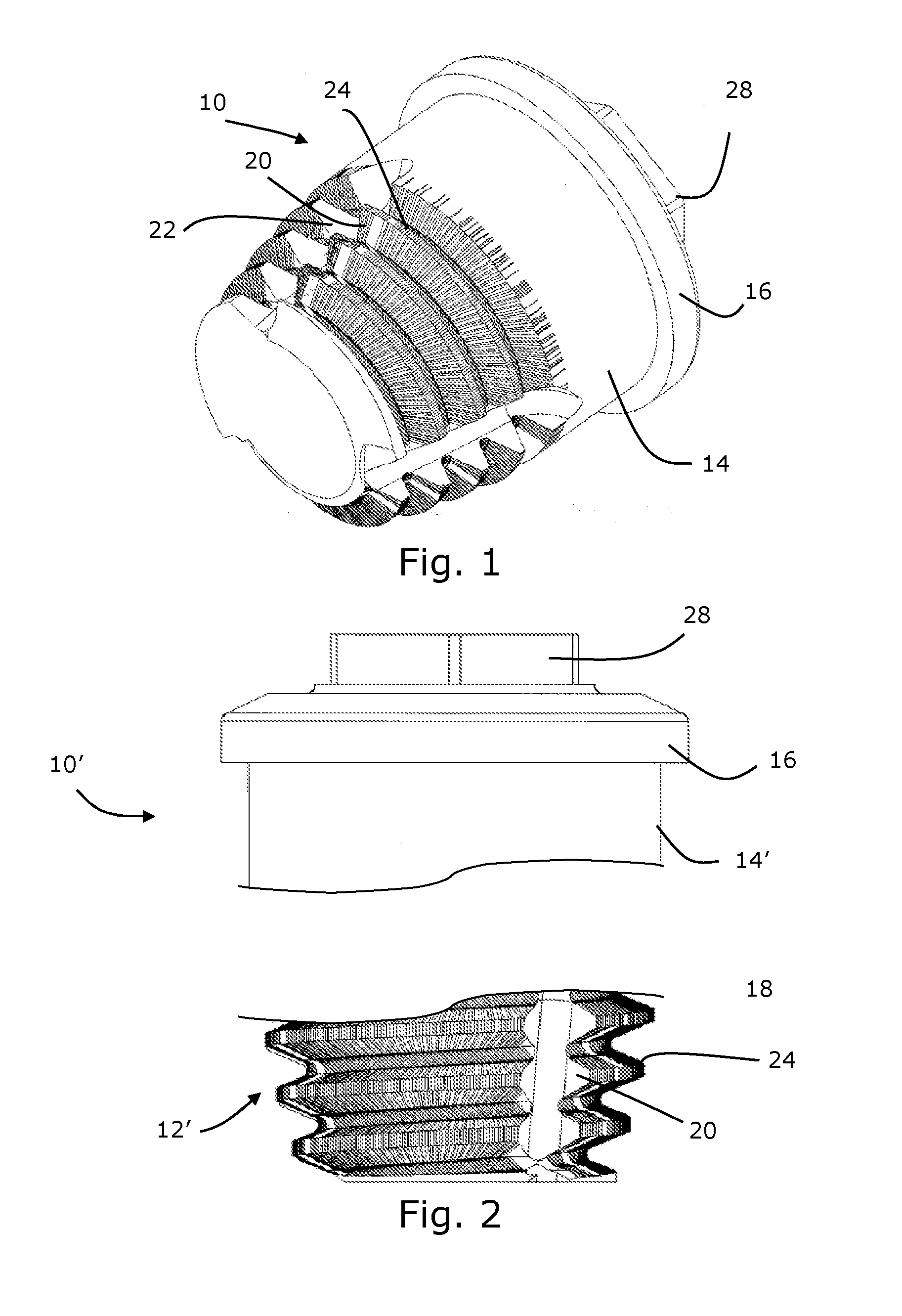
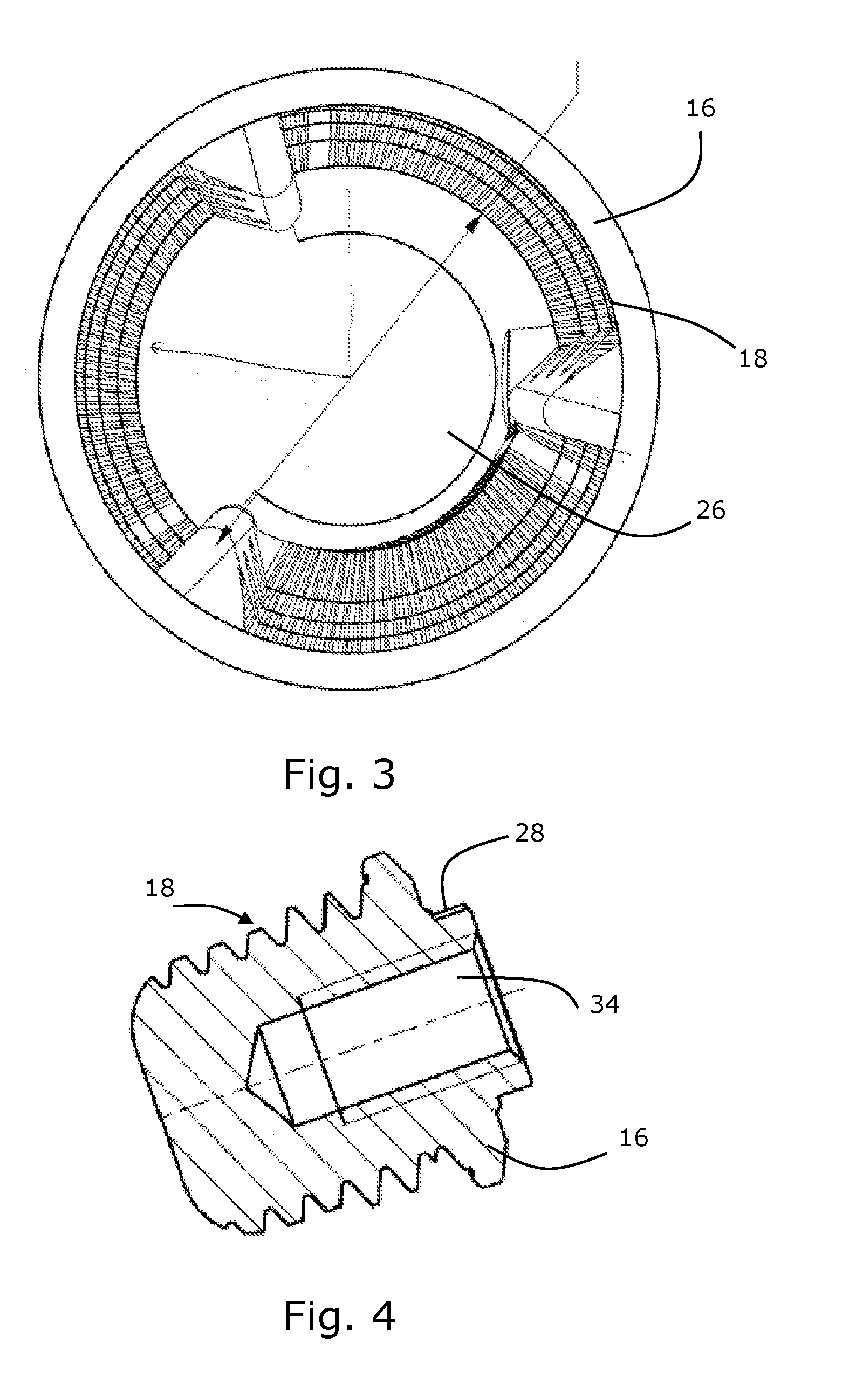
[0053]FIG. 1 is a schematic illustration of a bone implant device 10 according to the present invention.

[0054]The bone implant device 10 comprises a body having a first part 12 and an opposite second part 14. The first part 12 and the opposite second part 14 define a longitudinal axis, not illustrated. The first part 12 includes an external thread 18. The external thread 18 comprises a first thread part 20 having a first radius measured from the longitudinal axis and a second thread part 22 having a second radius measured from the longitudinal axis. The first radius is larger than the second radius. The first thread part 20 is a cutting part and the second thread part is a contact surface. The contact surface rests against the bone when the implant device 10 has been inserted. When inserting the implant device 10 the contact surface will slide over a part of the bone where the first part 20, i.e. the cutting part, has left a space. By reducing the radius the actual contact area duri...


PUM


Abstract

The present invention relates to a bone implant device, comprising a body having a first part and an opposite second part, the first part and an opposite second part defining a longitudinal axis, the first part including an external thread extending from a cylindrical part to the distal end of the body, the external thread comprising a first thread part having a first radius measured from the longitudinal axis and a second thread part having a second radius measured from the longitudinal axis. The first radius is larger than the second radius, the first thread part is a cutting part, and the second thread part is a contact surface. The first part may include one or more cavities for storing bone fragments while the bone implant is in use.

Description

FIELD OF THE INVENTION[0001]The present invention relates to a bone implant device.BACKGROUND OF THE INVENTION[0002]There are several situations where a bone implant is needed. Below is listed some situations where a bone implant is usually used.[0003]When a person has a fractured bone there is a need for bringing two or more bone parts together so that the bone may repair the fracture.[0004]When a person needs a tooth implant mounted in the jaw-bone, there is a need for an implant device to hold the tooth implant.[0005]When a person has a hearing impediment there may in some situations be a need for mounting a hearing directly to the bone of the skull. For mounting such a hearing aid there is a need for an implantable device for attaching the hearing aid to the skull. The implant should not damage the bone structure in a way that will lead to necrotise of the surrounding bone material. Usually a relatively large hole is predrilled before the implant is inserted. Threads on the impl...

Claims


Application Information

Patent Timeline
IPC IPC(8): A61B17/86
CPCA61B17/863A61B17/864A61B17/8685A61B17/8625
Inventor ANDERSEN, HENRIK
Owner ELOS MEDTECH PINOL AS
Why Eureka
Try Eureka