Treatment device high frequency

Inactive Publication Date: 2014-06-05
LUTRONIC
View PDF4 Cites 12 Cited by
  • Summary
  • Abstract
  • Description
  • Claims
  • Application Information

AI Technical Summary

Benefits of technology

[0021]According to the present invention, high-frequency energy may be applied to a proper position of the skin depending on the purpose of a surgical procedure. Accordingly, the eff

Problems solved by technology

If high-frequency energy is supplied to a skin surface, as the electric current of the high-frequency wave changes its flowing direction, molecules in the skin are rendered to vibrate, causing friction between the molecules.
However, it is difficult to conduct various surgical procedures with a single piece of equipment like the conventional high-frequency treatment.
The controller may compare a set operation mode with the type of the hand piece sensed by the sensing unit, and if determining that a hand piece corresponding to the set operation mode is not connected with the coupling unit, may generate an error signal.
Meanwhile, the contact-type hand piece may include a first sensor that senses a contact state between the first ele

Method used


Image

  • Treatment device high frequency
  • Treatment device high frequency
  • Treatment device high frequency

Examples


first embodiment

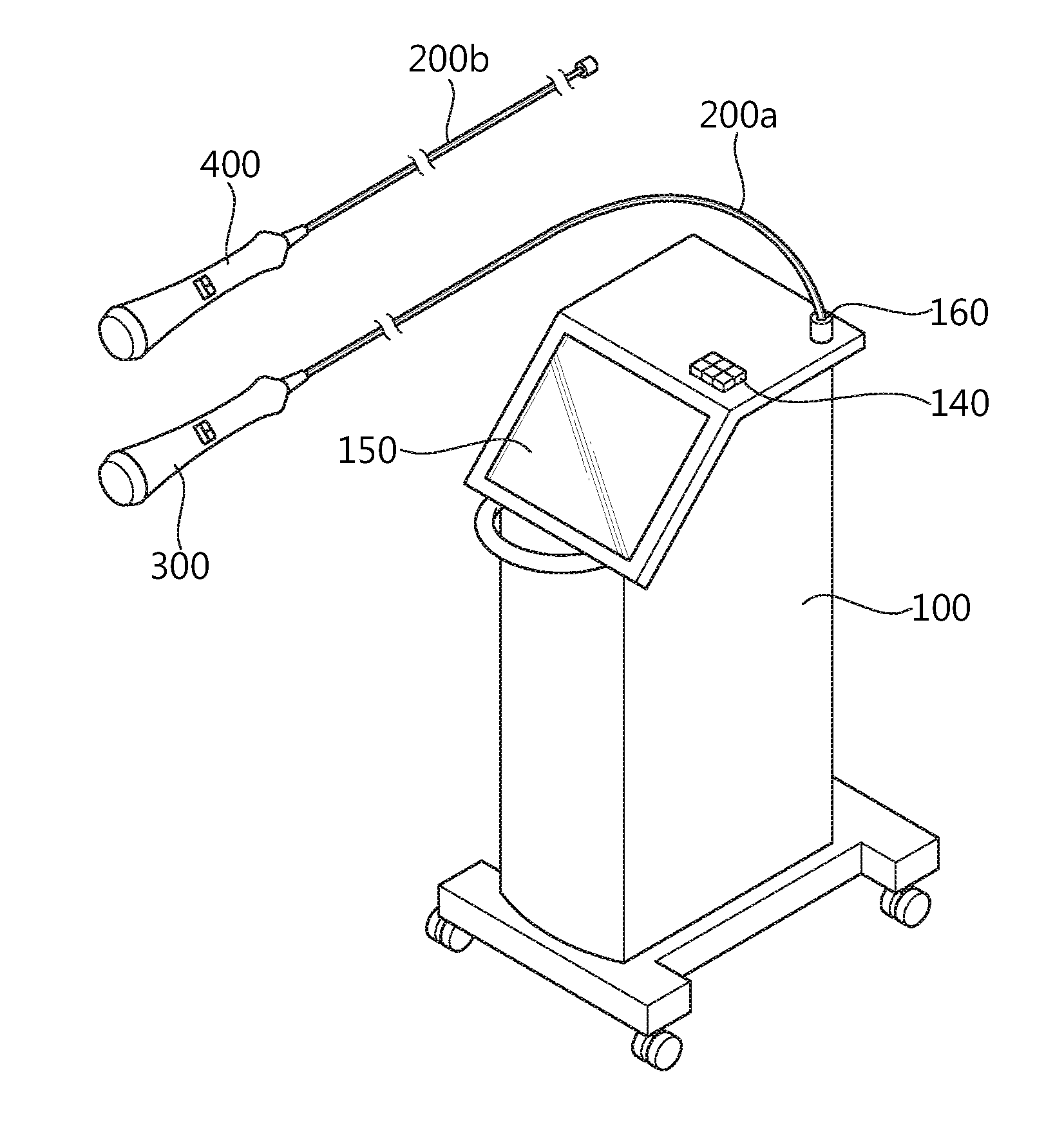
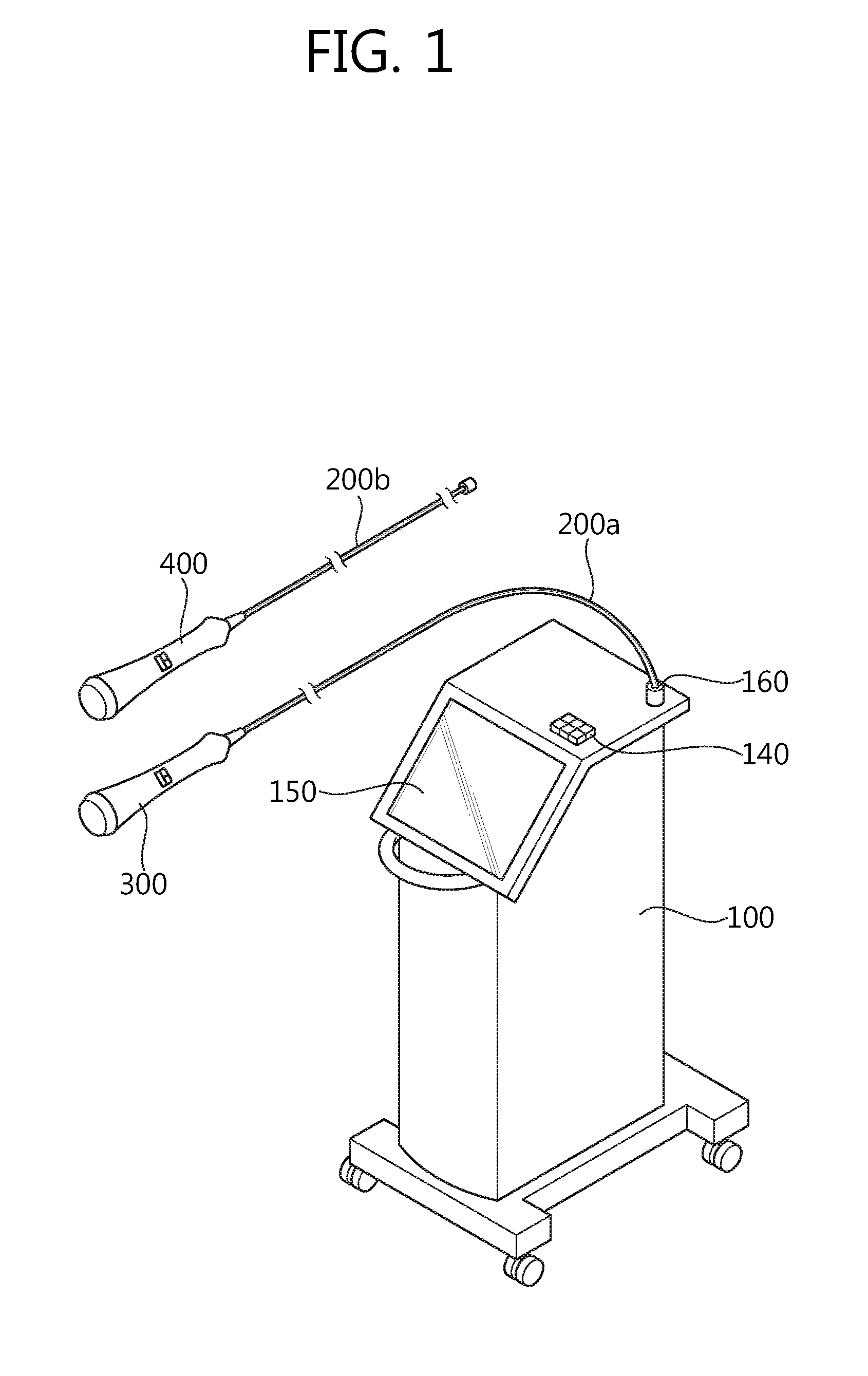
[0034]FIG. 1 is a perspective view illustrating a treatment device using high-frequency wave according to the present invention. A treatment device using high-frequency wave according to an embodiment of the present invention, as shown in FIG. 1, includes a main body 100, a contact-type hand piece 300 and an invasive hand piece 400 that are detachably provided at the main body 100.

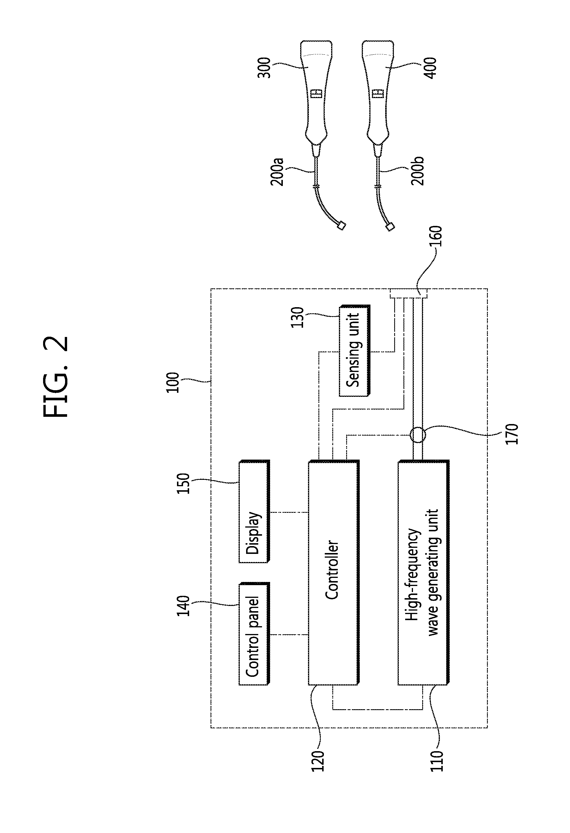
[0035]The main body 100 includes a power supply (not shown) to receive power from outside. On an outside surface of the main body 100 are provided a control panel 140 for operating the driving of the treatment device using high-frequency wave and a display 150 for displaying the driving to a user. In the main body 100 is provided a high-frequency wave generating unit 110 for generating high-frequency energy using power supplied from the power supply. On an outside surface of the main body 100 is formed a coupling unit for coupling the contact-type hand piece 300 with the invasive hand piece 400.

[0036]The c...

second embodiment

[0095]FIG. 10 is a perspective view illustrating a treatment device using high-frequency wave according to the present invention, and FIG. 11 is a view schematically illustrating the configuration of a treatment device using high-frequency wave as illustrated in FIG. 10.

[0096]In the above-described first embodiment, a contact-type hand piece and an invasive hand piece are selectively coupled with one treatment device using high-frequency wave. In the instant embodiment, however, each of a contact-type hand piece 1300 and an invasive hand piece 1400 is connected with one treatment device using high-frequency wave, as illustrated in FIG. 10.

[0097]As illustrated in FIG. 11, the main body 1100 includes a high-frequency wave generating unit 1110 that may provide high-frequency energy to a first electrode unit 1320 of the contact-type hand piece 1300 and a second electrode unit 1420 of the invasive hand piece 1400. The main body 1100 further includes a control panel 1140 that allows a use...


PUM


Abstract

The present invention relates to a treatment device using high frequency and provides a treatment device using high frequency comprising: a main body comprising a high frequency generation portion inside; a contact type hand piece comprising a first electrode portion for providing high frequency energy generated in the high frequency generation portion to the surface of the skin, and is detachably formed at an fastening portion of the main body; an invasive hand piece comprising a second electrode portion for providing high frequency energy generated in the high frequency generation portion to the inside of the skin, and is detachably formed at an fastening portion of the main body; and a control portion for controlling the high frequency energy provided from the high frequency generation portion to the first electrode portion or the second electrode portion.

Description

TECHNICAL FIELD[0001]The present invention relates to a treatment device using high-frequency wave, and more specifically, to a treatment device using high-frequency wave that may treat skin tissues using high-frequency energy.RELATED ART[0002]There are a wide range of applications of the technology of treating skins by providing energy to skins using various energy sources to deform the skin tissues or enhancing tissue characteristics. Skin treating devices using a diversity of energy sources such as laser beams, flash lamps, or ultrasonic waves have been being developed, and nowadays, research on skin treating devices adopting RF waves are intensively underway.[0003]If high-frequency energy is supplied to a skin surface, as the electric current of the high-frequency wave changes its flowing direction, molecules in the skin are rendered to vibrate, causing friction between the molecules. Accordingly, the molecules are rotated, twisted, or collide each other, generating deep heat. S...

Claims


Application Information

Patent Timeline
IPC IPC(8): A61N5/00
CPCA61N5/00A61H39/08A61H2201/0153A61H2201/0184A61H2201/10A61H2201/1685A61H2201/5005A61H2201/5025A61H2201/5035A61H2201/5071A61H2230/65A61N1/0502A61N1/06A61B18/04A61B18/18
Inventor KO, KWANG CHON
Owner LUTRONIC
Why Eureka
Try Eureka