Device and method for controlling a fluid actuator

a fluid actuator and actuator technology, applied in flow control using electric means, ratio control, instruments, etc., can solve the problems of not being able to control slave actuators using user-programmed state feedback control algorithms, not being able to receive and process input from external sensors or devices such as slave valves, and occupying valuable bandwidth. , the effect of improving the dynamic performance of the hydraulic axis

Active Publication Date: 2014-06-05
DANFOSS AS
View PDF3 Cites 4 Cited by
  • Summary
  • Abstract
  • Description
  • Claims
  • Application Information

AI Technical Summary

Benefits of technology

The patent describes a new hydraulic control system that uses a distributed control architecture to improve the digital performance of each hydraulic axis. The system is designed to reduce the amount of data transfer on the network or field bus and to simplify the responsibilities of the central PLC. The system also allows for user programming of the control algorithms, providing more flexibility and protecting the user's intellectual property. The technical effects of the system include improved dynamic performance, reduced network traffic, and increased user flexibility.

Problems solved by technology

This prior art device does not allow the user to program the second controller with a state feedback control algorithm for controlling the hydraulic actuator.
Also, in this prior art device, there is no capability to control slave actuators using a user programmed state feedback control algorithm in the device as disclosed and claimed.
Also, in this prior art device, there is no capability to receive and process the input from a variety of external sensors or devices such as slave valves.
The drawbacks of the prior art centralized control architecture are that it results in significant cost to route cabling throughout the machine and significant wiring complexity in the PLC panel.
Furthermore a costly, high end PLC is required to simultaneously coordinate all of the hydraulic axes and run the several state feedback control algorithms at a sufficient control rate to achieve required dynamic performance of each hydraulic axis.
The drawback to this variation of a centralized control architecture with digital communication between nodes and PLC is that control update rates are now limited by the bandwidth of the field bus or network.
The end result is that the performance of the hydraulic axis suffers from the latency of manipulations received from the central controller.

Method used


Image

  • Device and method for controlling a fluid actuator
  • Device and method for controlling a fluid actuator
  • Device and method for controlling a fluid actuator

Examples


Embodiment Construction

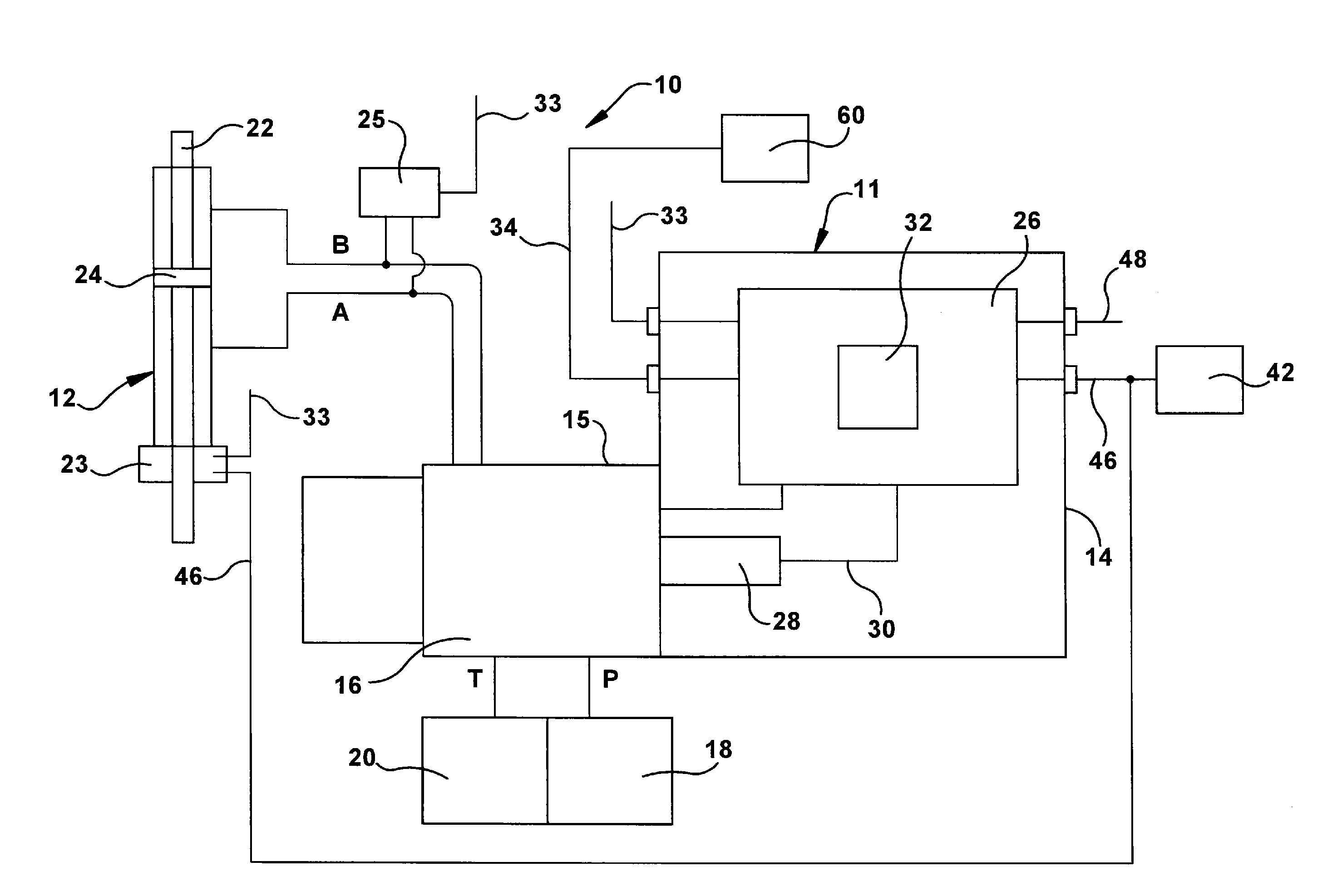
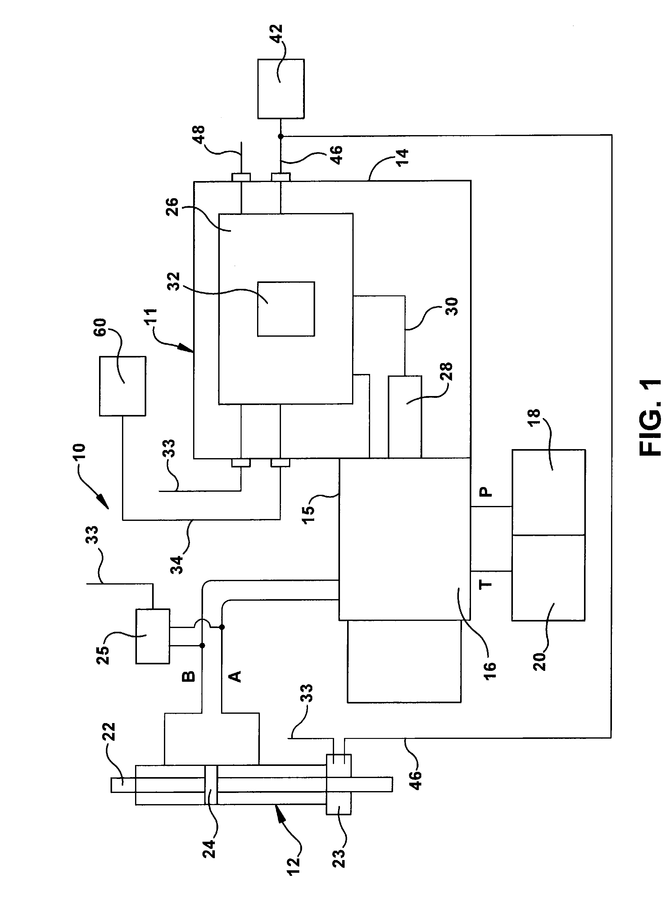
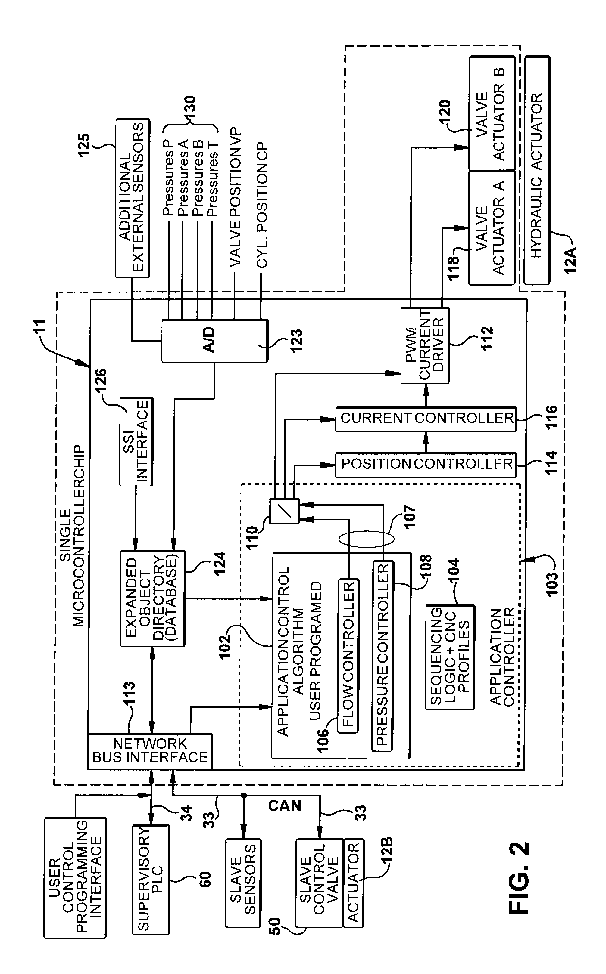
[0012]Referring now to the discussion that follows and also to the drawings, illustrative approaches to the disclosed systems and methods are shown in detail. Although the drawings represent some possible approaches, the drawings are not necessarily to scale and certain features may be exaggerated, removed, or partially sectioned to better illustrate and explain the present disclosure. Further, the descriptions set forth herein are not intended to be exhaustive or otherwise limit or restrict the claims to the precise forms and configurations shown in the drawings and disclosed in the following detailed description.

[0013]Moreover, a number of constants may be introduced in the discussion that follows. In some cases illustrative values of the constants are provided. In other cases, no specific values are given. The values of the constants will depend on characteristics of the associated hardware and the interrelationship of such characteristics with one another as well as environmenta...


PUM


Abstract

A hydraulic actuator control system for controlling the motion of a master actuator and at least one slave actuator may include an external supervisory computer for sending command signals. A hydraulic control system may be connected to the master actuator and the supervisory computer. The hydraulic control system may include a microprocessor and a master hydraulic control valve for controlling the flow of a pressurized fluid to the master actuator based on the command signals. The hydraulic actuator control system may include at least one slave actuator having at least one slave sensor connected to the microprocessor and having at least one slave control valve for controlling the flow of pressurized fluid to the slave actuator. The slave control valve and the slave sensor may be controlled by the microprocessor.

Description

[0001]This application is a divisional application of U.S. patent application Ser. No. 13 / 410,327, which is hereby incorporated by reference in its entirety.TECHNICAL AREA[0002]A hydraulic actuator control device for implementing a distributed control architecture for regulating the performance of one or more hydraulic actuators according to command signals from a single, on-board, user programmable microprocessor.PRIOR ART[0003]A device for controlling a hydraulic actuator is disclosed in DE 195 30 935 C2. Disclosed in this reference is a displacement sensor for indicating the position of the valve piston with an electrical signal which is supplied to a position controller. The controller for controlling the position of the valve piston is arranged in its own housing, which is mounted on the housing of the valve. The controller ensures that the valve piston follows a position set point, which is supplied to the controller as an electrical input variable. In this case, the position ...

Claims


Application Information

Patent Timeline
Patent Type & Authority Applications(United States)
IPC IPC(8): G05D7/06
CPCF15B21/08F15B15/28G05D7/0635
Inventor ALSTRIN, KEVIN E.LAUER, PETERROBB, BERT W.
Owner DANFOSS AS
Why Eureka
Try Eureka