Carbon heating element for evaporative emission canister

a technology of evaporative emission and heating element, which is applied in the direction of combustion air/fuel air treatment, machines/engines, manufacturing tools, etc., can solve the problem that fuel vapor is a pollutant, and achieve the effect of reducing the amount of fuel vapor emitted

Active Publication Date: 2014-06-12
DELPHI TECH IP LTD
View PDF6 Cites 15 Cited by
  • Summary
  • Abstract
  • Description
  • Claims
  • Application Information

AI Technical Summary

Benefits of technology

[0003]In a first aspect of the invention, an evaporative emissions control system for reducing the amount of fuel vapor emitted from a vehicle is presented, where the vehicle has an engine with an air intake passage and a fuel system. The control system includes a canister having a purge port, a tank port, and a vent port in communication with a sorbent material disposed within the canister. The purge port communicates with the intake passage via a purge valve. The tank port communicates with the fuel system and allows a mixture of air and the fuel vapor it carries to be conveyed between the fuel system and the canister. The vent port connects to one end of a vent valve whose other end communicates to atmosphere. The canister has a substantially cylindrical cartridge heater disposed within it such that the heater is disposed in direct physical contact with the sorbent material so as to allow heat conduction from the heater to the sorbent material. During at least one predetermined time interval electrical power is supplied to the heater through electrical terminals located exterior to the canister to heat the sorbent material when the control system is operated in a regenerative phase of operation. During a storage phase of operation, the control system allows of the mixture of air and fuel vapor to flow from the fuel system through the tank port and into the canister. As the mixture flows through the canister, the sorbent material adsorbs a percentage of the fuel vapor. The mixture of air and any unadsorbed fuel vapor then flows through the vent port and through the vent valve to atmosphere. During the regenerative phase, the control system allows air drawn in from atmosphere to flow through the vent valve and the vent port into the canister. As the mixture flows through the canister, fuel vapor is desorbed from the sorbent material. The mixture of air and desorbed fuel vapor is drawn out through the purge port into the intake passage by the engine for combustion within the engine.
[0004]In a related aspect, the invention provides a method of manufacturing an evaporative emissions control system. The method includes receiving a canister having a hole defined in an exterior wall of the canister. The method further includes receiving a substantially cylindrical cartridge heater having electrical terminals disposed at or near one end of the heater. The method further includes disposing a heat sink in contact with the cartridge heater and disposing the cartridge heater through the hole in the canister, so that the heat sink is internal to the canister and the electrical terminals are external to the canister.

Problems solved by technology

If the air emitted from the fuel tank were allowed to flow untreated into the atmosphere, it would inevitably carry with it this fuel vapor.
The fuel vapor, however, is a pollutant.

Method used


Image

  • Carbon heating element for evaporative emission canister
  • Carbon heating element for evaporative emission canister
  • Carbon heating element for evaporative emission canister

Examples


Embodiment Construction

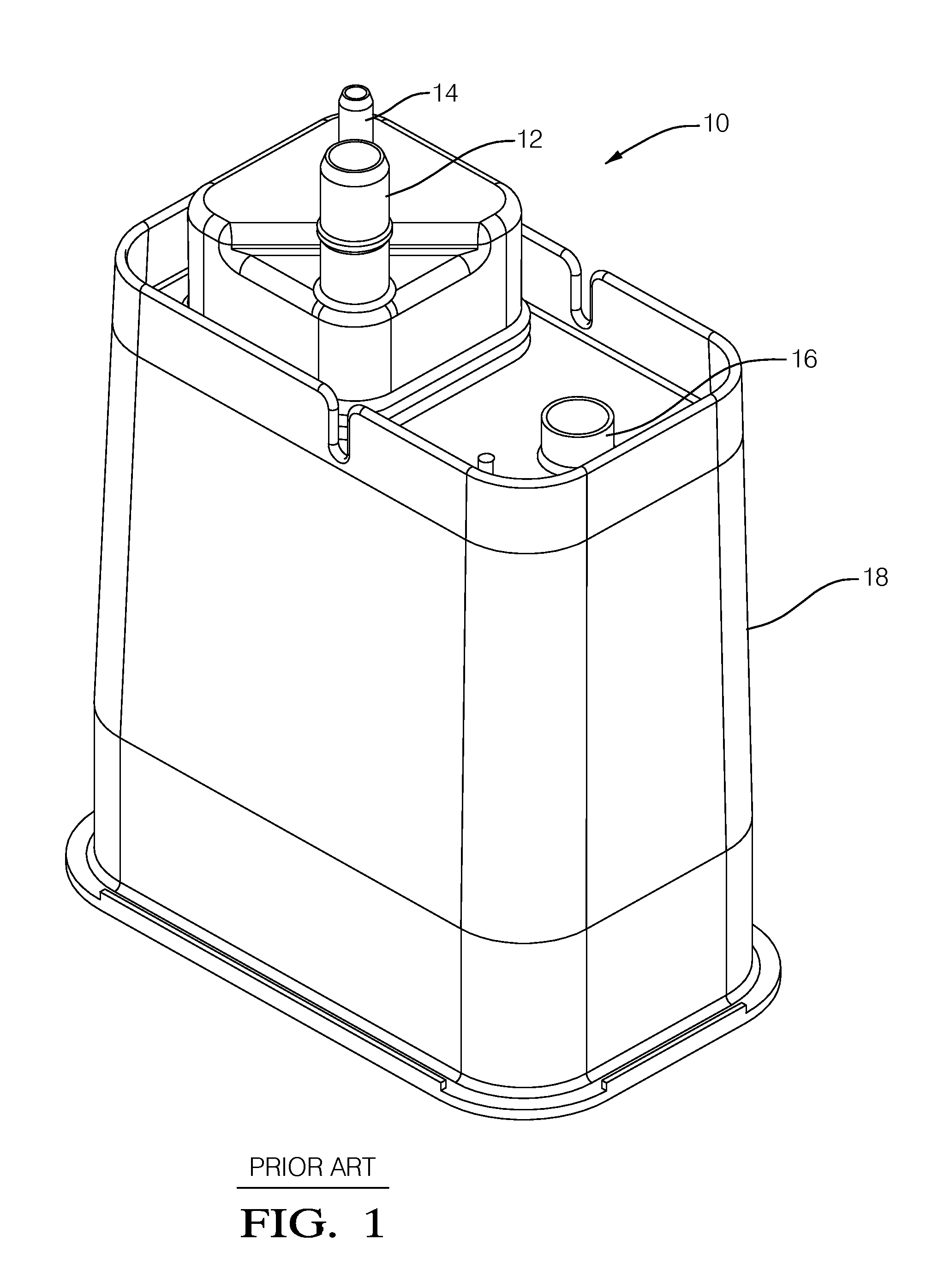
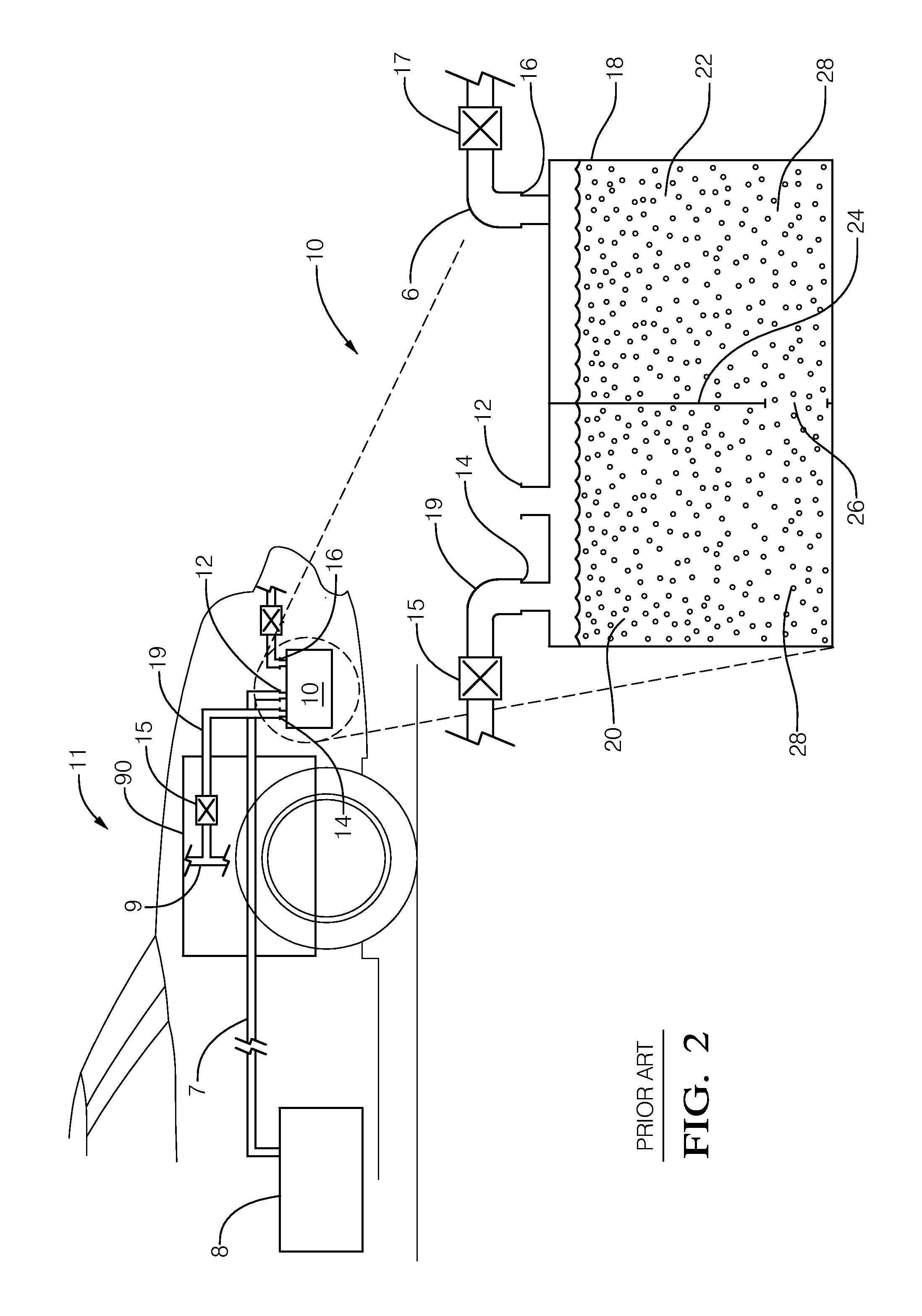
[0012]FIGS. 1 and 2 illustrate one type of storage canister, generally designated 10, typically used in the automotive industry. FIG. 1 shows the canister in a perspective view, whereas FIG. 2 shows it in cross-section. The storage canister 10 comprises a container 18 that is partially divided by partition 24 into two compartments 20 and 22. An intercompartmental flow passage 26 connects these compartments.

[0013]The storage canister 10 has a tank port 12 and a purge port 14, both of which communicate with the first compartment 20. The tank port 12 connects to the tank tube 7, and thereby allows the air space in the fuel tank 8 to communicate with the first compartment 20. To the left of the tank port 12 as viewed from the perspective of FIG. 2, the purge port 14 connects to a purge line 19. Through a purge valve 15, the purge line 19 connects to the air intake passage 9 of the vehicle 11. (Air flowing into the air intake passage 9 is mixed with fuel, and the mixture eventually drawn...


PUM

PropertyMeasurementUnit
electrical poweraaaaaaaaaa
temperatureaaaaaaaaaa
pressureaaaaaaaaaa

Abstract

An evaporative emissions control system for reducing the amount of fuel vapor emitted from a vehicle includes a canister containing a sorbent material and a cartridge heater disposed at least partially within the canister in direct contact with the sorbent material. Electrical terminals for applying power to a heating element within the heater are disposed external to the canister. At least one heat sink may be included within the canister in direct contact with the heater. A method of manufacturing an evaporative emission control system that includes a cartridge heater disposed in a canister is also presented.

Description

BACKGROUND OF THE INVENTION[0001]Evaporative emissions of fuel vapor from a vehicle having an internal combustion engine occur principally due to venting of the fuel tank of the vehicle. When the vehicle is parked, diurnal changes in temperature or pressure of the ambient atmosphere cause air to waft into and out of the fuel tank. Some of the fuel inevitably evaporates into the air within the tank and thus takes the form of a vapor. If the air emitted from the fuel tank were allowed to flow untreated into the atmosphere, it would inevitably carry with it this fuel vapor. The fuel vapor, however, is a pollutant. For that reason, federal and state governments have imposed increasingly strict regulations over the years governing how much fuel vapor may be emitted from the fuel system of a vehicle.[0002]One approach that automobile manufacturers have long employed to reduce the amount of fuel vapor that a vehicle emits to the atmosphere involves the use of a storage canister. In this ap...

Claims


Application Information

Patent Timeline
Patent Type & Authority Applications(United States)
IPC IPC(8): F02M27/00
CPCF02M25/0854F02M2025/0881Y10T29/49826F02M27/00
Inventor MEILLER, THOMAS C.
Owner DELPHI TECH IP LTD
Why Eureka
Try Eureka