Solar Cell and Method of Manufacturing the Same

a solar cell and manufacturing method technology, applied in the field of solar cells, can solve the problems of generally lower energy conversion efficiency of the rear surface of the solar cell, i.e., approximately 2 %, and achieve the effect of low photoelectric conversion efficiency

Active Publication Date: 2014-06-12
SHIN SUNG SOLAR ENERGY
View PDF9 Cites 7 Cited by
  • Summary
  • Abstract
  • Description
  • Claims
  • Application Information

AI Technical Summary

Benefits of technology

[0011]It is another object of the present invention to provide a solar cell and a method of manufacturing the same that may address problems of a bifacial solar cell, i.e., lower photoelectric conversion efficiency at a rear surface than at a front surface.

Problems solved by technology

However, when a bifacial solar cell is formed using such conventional manufacturing method, energy conversion efficiencies at front and rear surfaces thereof differ, and the energy conversion efficiency of the rear surface thereof is generally lower (i.e., approximately 2%) than that of the front surface of the solar cell.

Method used


Image

  • Solar Cell and Method of Manufacturing the Same
  • Solar Cell and Method of Manufacturing the Same
  • Solar Cell and Method of Manufacturing the Same

Examples


Embodiment Construction

[0023]Hereinafter, embodiments of the present invention will be described in detail with reference to the accompanying drawings.

[0024]When it is deemed that a detailed description of the related known functions or configurations may unnecessarily obscure the subject matter of the present invention, a detailed description thereof will be omitted. In addition, the following terms, which are defined in consideration of functions of the present invention, may be altered depending on user or operator intentions or judicial precedents. Therefore, the meaning of each term should be interpreted based on the overall disclosure of the specification.

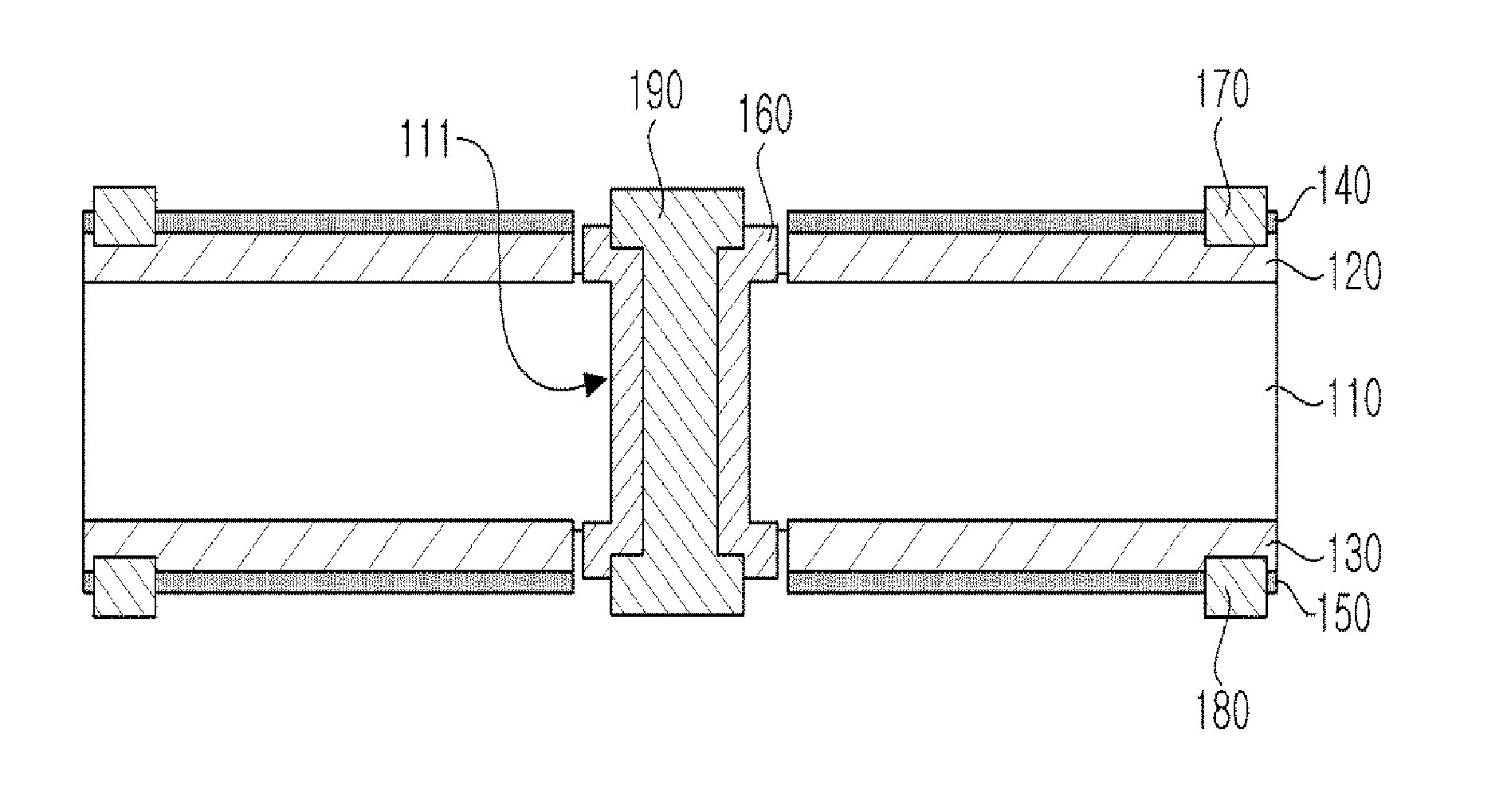
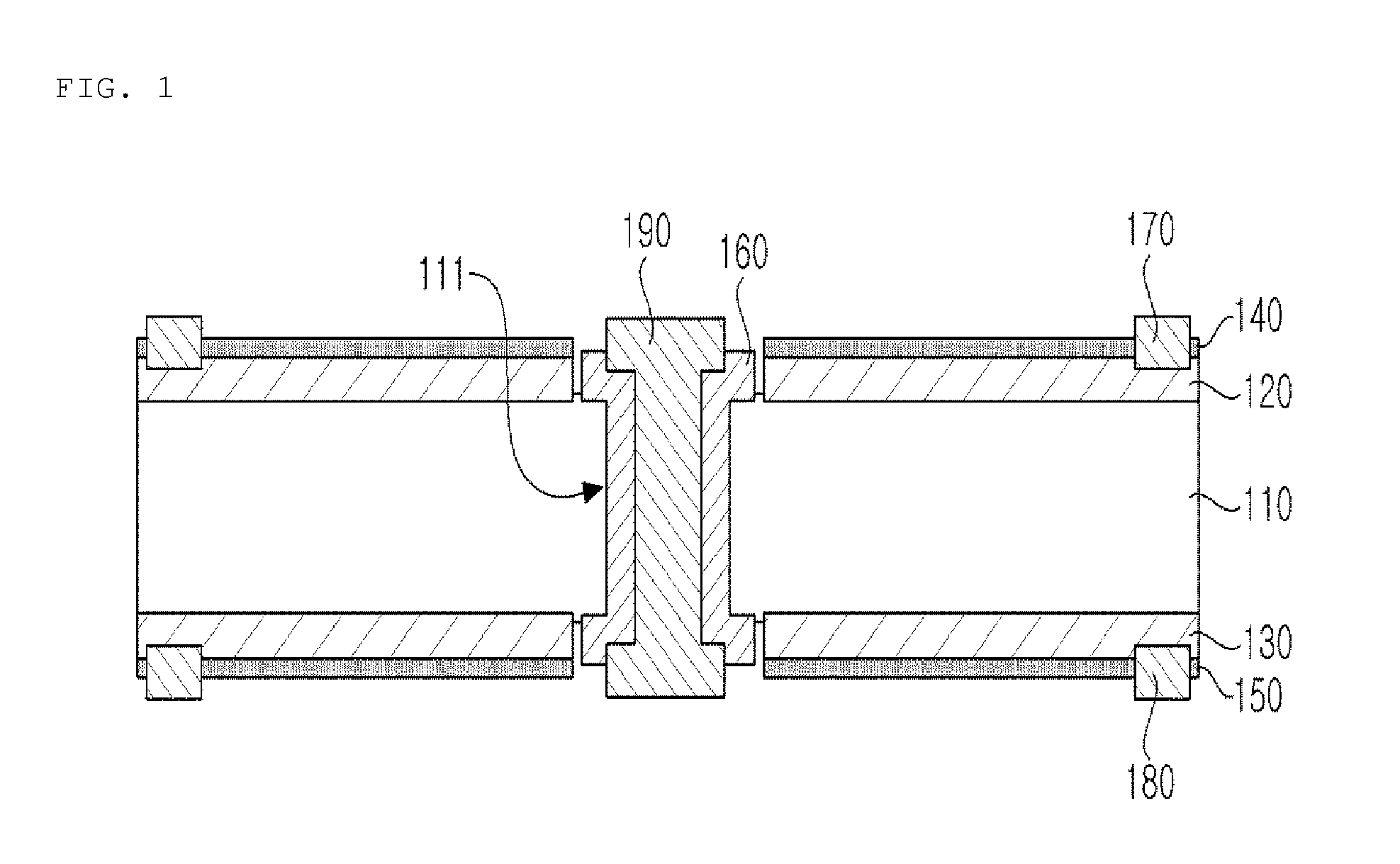
[0025]First, FIG. 1 is a sectional view illustrating a structure of a solar cell according to an embodiment of the present invention.

[0026]Referring to FIG. 1, the solar cell 100 according to the present embodiment includes a semiconductor substrate 110, upper and lower emitter layers 120 and 130, upper and lower anti-reflection coatings 140 and 15...


PUM


Abstract

A solar cell and a method of manufacturing the same are disclosed.
The solar cell includes a semiconductor substrate doped with a first conductive type impurity through which a via hole passing from a first surface of the semiconductor substrate to a second surface thereof facing the first surface is formed, wherein the first surface is a light receiving surface, upper and lower emitter layers respectively formed on upper and lower surfaces of the semiconductor substrate and doped with a second conductive type impurity that is different from the first conductive type impurity, current collecting layers formed on sidewalls of the via hole and doped with a higher concentration of the first conductive type impurity than that of the semiconductor substrate, a contact electrode extending from the first surface of the semiconductor substrate to the second surface thereof so as to fill the via hole, and upper and lower electrodes respectively contacting the upper and lower emitter layers.

Description

BACKGROUND OF THE INVENTION[0001]1. Field of the Invention[0002]The present invention relates to a solar cell and a method of manufacturing the same, and more particularly to a bifacial solar cell and a method of manufacturing the same.[0003]2. Description of the Related Art[0004]Recently, interest in alternative energy sources that can replace existing energy sources such as petroleum or coals has increased due to depletion of existing energy sources. Among these alternative energy sources, solar cells are receiving attention because solar energy is abundant and solar cells do not cause problems in terms of environmental pollution. Solar cells are classified into solar thermal cells to generate steam needed for rotation of a turbine using solar heat and photovoltaic solar cells that use semiconductors to convert photons into electrical energy. Photovoltaic solar cells are generally referred to as “solar cells” (hereinafter referred to as “solar cells”).[0005]Solar cells are semicon...

Claims


Application Information

Patent Timeline
Patent Type & Authority Applications(United States)
IPC IPC(8): H01L31/065H01L31/0216
CPCH01L31/0684H01L31/1804Y02E10/547H01L31/022433H01L31/022425Y02P70/50H01L31/18H01L31/042Y02E10/52
Inventor KIM, JI SOOKIM, HO SIKKIM, JI SUNLIM, JONG YOUBHWANG, YEON HEECHOI, HOON JOOJO, JEONG JAE
Owner SHIN SUNG SOLAR ENERGY
Why Eureka
Try Eureka