Lifting Column for Lifting a Load, Lifting System Provided Therewith and Method for Measuring a Load

a technology for lifting columns and loads, applied in generators/motors, capacitor dielectric layers, instruments, etc., can solve problems such as vehicle and equipment damage, operator injuries, etc., and achieve the effect of adding safety to lifting operations

Active Publication Date: 2014-06-12
STERTIL
View PDF24 Cites 14 Cited by
  • Summary
  • Abstract
  • Description
  • Claims
  • Application Information

AI Technical Summary

Benefits of technology

[0036]Such method provides the same effects and advantages as those stated with reference to the lifting column and/or lifting system. Preferably, the method uses the load sensor according to the invention as described earlier. Preferably, the measurement data

Problems solved by technology

Lifting a load with a weight above this maximum leads to unsafe operation of the lifting columns possibly

Method used


Image

  • Lifting Column for Lifting a Load, Lifting System Provided Therewith and Method for Measuring a Load
  • Lifting Column for Lifting a Load, Lifting System Provided Therewith and Method for Measuring a Load
  • Lifting Column for Lifting a Load, Lifting System Provided Therewith and Method for Measuring a Load

Examples


Embodiment Construction

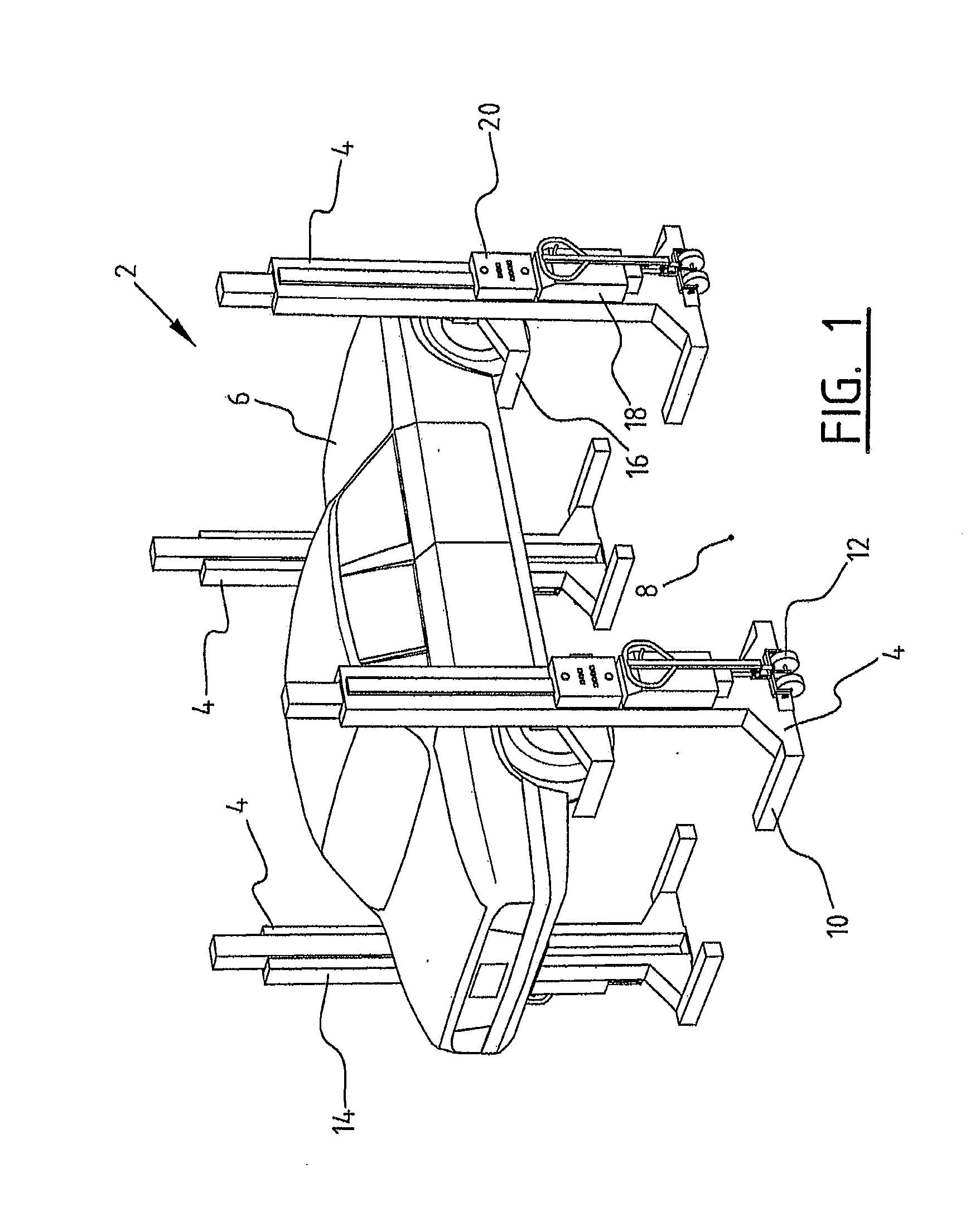
[0043]A system 2 for efficient lifting and lowering a load (FIG. 1) comprises four mobile lifting columns 4 in the illustrated embodiment. Lifting columns 4 lift a passenger car 6 from the ground 8. Lifting columns 4 are connected to each other and / or a control system by wireless communication means or alternatively by cables. Lifting columns 4 comprise a foot 10 which can travel on running wheels 12 over ground surface 8 of for instance a floor of a garage or workshop. In the forks of foot 10 is provided an additional running wheel (not shown). Lifting column 4 furthermore comprises a mast 14. A carrier 16 is moveable upward and downward along mast 14. Carrier 16 is driven by a motor 18 that is provided in a housing of lifting column 4. Motor 18 is supplied with power from the electrical grid or by a battery that is provided on lifting column 4 in the same housing as motor 18, or alternatively on foot 10 (not shown). Control panel 20 is provided to allow the user of system 2 to con...


PUM


Abstract

Disclosed is a lifting column for lifting a load, such as a vehicle, which includes a frame with a movable carrier and a drive which acts on the carrier; control means for control of the drive; a carrying part attached to the carrier for carrying the load; weight measuring means attached to the carrying part for measuring the weight of the load; and communication means for communicating a measurement signal of the weight measuring means indicative of the weight of the load to the control means.

Description

CROSS-REFERENCE TO RELATED APPLICATIONS[0001]This application claims priority to U.S. Provisional Patent Application No. 61 / 735,102 and The Netherlands Patent Application No. 2009949, both filed Dec. 10, 2012, the disclosures of which are hereby incorporated by reference in their entiretyBACKGROUND OF THE INVENTION[0002]1. Field of the Invention[0003]The present invention relates to a lifting column for lifting a load, such as a vehicle. Such lifting columns are in particular used for lifting motor vehicles including buses and trucks and may relate to lifting columns of the two-post lift type with pivoting support arms, the four-post lift type with runways, the mobile type etc.[0004]2. Description of Related Art[0005]A lifting column known from practice comprises a frame with a carrier that is connected to a drive for moving the carrier upwards and downwards. In the ascent mode hydraulic oil is pumped to a cylinder for lifting the carrier, and thereby the vehicle. In the descent mod...

Claims


Application Information

Patent Timeline
IPC IPC(8): B66F17/00B66F3/00G01G19/08B66F7/24
CPCB66F17/00B66F7/24B66F3/00G01G19/083B66F3/46B66F7/28H01G9/028H01G17/00H02N2/18H01G9/07
Inventor DE JONG, JURJEN JAN
Owner STERTIL
Why Eureka
Try Eureka