Reducing agent supply apparatus and internal-combustion engine exhaust gas purification apparatus

a technology of exhaust gas purification and reducing agent, which is applied in the direction of liquid fuel feeders, machines/engines, electric control, etc., can solve the problems of reducing diagnostic accuracy and reducing the pressure pu of reducing agent, and achieve the effect of efficient purification

Active Publication Date: 2014-06-19
BOSCH CORP
View PDF5 Cites 20 Cited by
  • Summary
  • Abstract
  • Description
  • Claims
  • Application Information

AI Technical Summary

Benefits of technology

[0021]According to the internal-combustion engine exhaust gas purification apparatus in accordance with the invention, the reducing agent supply apparatus that can reduce the state of large deviation of the pressure of reducing agent supplied to the reducing agent injection valve from a target pressure is included, which allows liquid reducing agent to be injected in just proportion and allows nitrogen oxides to be efficiently purified. Furthermore, according to the internal-combustion engine exhaust gas purification apparatus in accordance with the invention, the reducing agent supply apparatus as described above is included, which can precisely perform diagnostic control using the reducing agent pressure.

Problems solved by technology

However, attempting to maintain the reducing agent pressure Pu at the target pressure Pu_tgt only by feedback-controlling the output of the pump 223 may cause the reducing agent pressure Pu to largely deviate from the target pressure Pu_tgt when the injection amount of the liquid reducing agent significantly increases or decreases.
Furthermore, in a case such as when a diagnostic control using the reducing agent pressure Pu or the like is performed, the diagnostic accuracy may decrease.

Method used


Image

  • Reducing agent supply apparatus and internal-combustion engine exhaust gas purification apparatus
  • Reducing agent supply apparatus and internal-combustion engine exhaust gas purification apparatus
  • Reducing agent supply apparatus and internal-combustion engine exhaust gas purification apparatus

Examples


first embodiment

3. Effect of First Embodiment

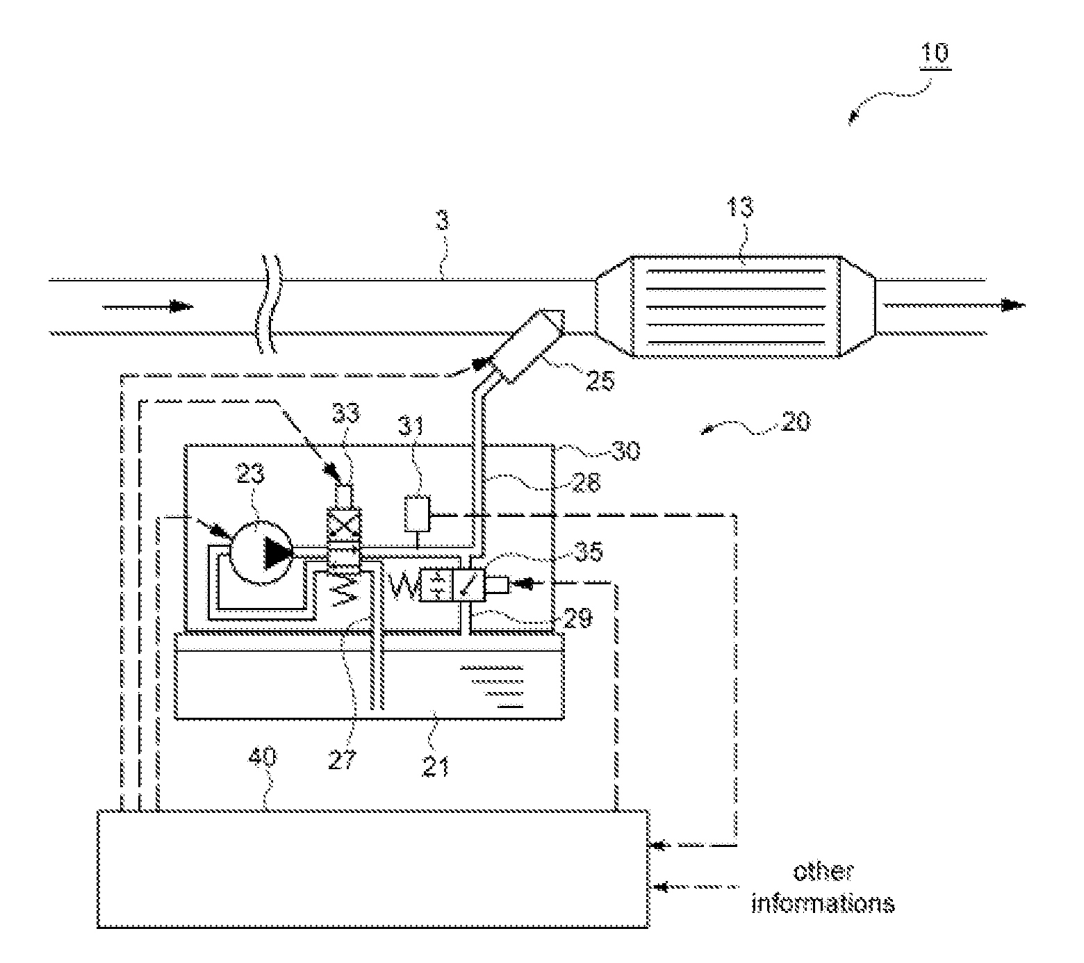
[0078]The reducing agent supply apparatus 20 in accordance with the first embodiment of the invention described above is configured to adjust the opening of the passage throttle valve 35 provided in the middle of the reducing agent return passage 29 according to the difference ΔDVduty between the drive duty ratios of the reducing agent injection valve 25 in conjunction with feedback-controlling the output of the electromagnetic pump 23, which can reduce the state of large deviation of the reducing agent pressure Pu from the target pressure Pu_tgt. Consequently, controlling the reducing agent injection valve 25 assuming that the reducing agent pressure Pu has reached the target pressure Pu_tgt causes liquid reducing agent to be injected into within the exhaust gas passageway 3 in just proportion. Furthermore, when various diagnostic controls using the reducing agent pressure Pu, such as diagnosing clogging of the reducing agent injection valve 25, are per...

second embodiment

3. Effect of Second Embodiment

[0108]For the reducing agent supply apparatus in accordance with the second embodiment of the invention described above, the same effect as that of the reducing agent supply apparatus 20 in accordance with the first embodiment can be achieved, and in addition, the durations Tbfv_close and Tbfv_open in which the opening of the passage throttle valve 35 is to be changed are corrected according to the state of the difference between the reducing agent pressure Pu and the target pressure Pu_tgt as a result of changing the opening of the passage throttle valve 35, which can prevent the reducing agent pressure Pu from largely deviating from the target pressure Pu_tgt for a long period of time. Thus, even with individual variability or time degradation in the reducing agent supply apparatus, the exhaust gas purification apparatus that can precisely perform exhaust gas purification control for a long period can be provided.

third embodiment

[0109]A reducing agent supply apparatus in accordance with a third embodiment of the invention has a basic configuration similar to that of the reducing agent supply apparatus in accordance with the first or second embodiment, and is further configured to perform control of the passage throttle valve and control of the passage switching valve through one harness.

[0110]FIGS. 12(a) and 12(b) schematically show an electric circuit that connects the electronic control unit 40 or 50, the passage switching valve 33 and the passage throttle valve 35 in the reducing agent supply apparatus in accordance with this embodiment. Among them, FIG. 12(a) shows a situation in which the injection control of liquid reducing agent is being performed, and FIG. 12(b) shows a situation in which the collection control of liquid reducing agent is being performed.

[0111]A signal line 37 and a ground line 38 are placed between the electronic control unit 40 or 50 and the pump unit 30. A switch driver 39 is pro...


PUM


Abstract

A reducing agent supply apparatus that can reduce the state of large deviation of the pressure within a reducing agent supply passage from a target pressure and an exhaust gas purification apparatus including such a reducing agent supply apparatus are provided.
A reducing agent supply apparatus including a pump, a reducing agent injection valve, a reducing agent supply passage, a reducing agent return passage and a pressure sensor, in which injection control of the liquid reducing agent by the reducing agent injection valve is performed while the reducing agent pressure is controlled so as to be maintained at a predetermined target pressure, includes: a passage throttle valve provided on the reducing agent return passage and having an opening controlled by energization; a pump control means for feedback-controlling the output of the pump based on the difference between the reducing agent pressure and the target pressure; and a passage throttle valve control means for controlling the opening of the passage throttle valve according to the change in the operation amount of the reducing agent injection valve.

Description

BACKGROUND OF THE INVENTION[0001]The present invention relates to a reducing agent supply apparatus for supplying reducing agent to an exhaust gas passageway of an internal-combustion engine and an internal-combustion engine exhaust gas purification apparatus including such a reducing agent supply apparatus.[0002]Conventionally, in an exhaust gas passageway of an internal-combustion engine included in a vehicle or the like, an exhaust gas purification apparatus for purifying nitrogen oxides (NOx) contained within exhaust gas is provided. One aspect of such an exhaust gas purification apparatus is an exhaust gas purification apparatus that includes: an NO purification catalyst for speeding up reduction reaction of NOx; and a reducing agent supply apparatus for supplying liquid reducing agent to within an exhaust gas passageway upstream of the NOx purification catalyst.[0003]FIG. 13 illustrates an example of a reducing agent supply apparatus 220. The reducing agent supply apparatus 22...

Claims


Application Information

Patent Timeline
Patent Type & Authority Applications(United States)
IPC IPC(8): F01N3/10
CPCF01N3/10F01N3/208F02D41/0002F01N2610/144F01N2900/1808F02M37/0029Y02T10/12
Inventor NAGATA, MASAYASU
Owner BOSCH CORP
Why Eureka
Try Eureka