Closed-loop hydraulic running tool

a hydraulic running tool and closed-loop technology, applied in the field of running tools, can solve the problems of hydraulic lines that require more time and expense for running or retrieval operations, and the control mechanism of the running tool can be problematic or time-consuming, and achieve the effect of increasing the fluid pressure in the tubular member

Active Publication Date: 2014-06-19
VETCO GRAY
View PDF5 Cites 34 Cited by
  • Summary
  • Abstract
  • Description
  • Claims
  • Application Information

AI Technical Summary

Benefits of technology

[0008]With the actuation sleeve and latch in the correct positions, a setting tool can be installed into a bore of the running tool to seal off a sub at the lower end of the running tool. The setting tool can be fitted with a lift eye for handling purposes. A standard handling sub can now be attached to a running tool drill stem connection, with a line attached. The handling sub can also keep the setting tool in position.
[0014]If BOP stack pressure was used during run in, it is vented after the tubing hanger is fully landed. The operator then applies pressure down the drill pipe or running string. The pressure will shear out the running tool actuation sleeve shear screw, allowing the pressure to urge the actuation sleeve downward. The actuation sleeve then urges the tubing hanger actuation sleeve downward, overcoming a low capacity shear screw or detent mechanism that holds the tubing hanger actuation sleeve in place. The tubing hanger actuation sleeve urges latch dogs outward to latch the tubing hanger in place. Once latched, the operator can pull upward on the drill pipe (standard overpull) to confirm correct locking of the tubing hanger. After releasing the overpull force, the running tool is now ready to be recovered.
[0018]In embodiments, the pistons prevent the closed-loop hydraulic fluid from contacting each of the fluids in the tubular member and in the running string. In embodiments, fluid pressure in the tubular member urges one of the pistons from a first position to a second position, the movement of the one of the pistons from the first position to the second position causing the closed-loop hydraulic fluid to move, the movement of the closed-loop hydraulic fluid urging an actuation sleeve from an unlatched position to a latched position to latch the wellhead member. In embodiments, fluid pressure in the tubular member is increased by closing a blowout preventer and applying a choke and kill pressure.

Problems solved by technology

Control mechanisms to actuate the running tool can be problematic or time consuming.
For example, hydraulic lines can be deployed through the riser to the running tool, or sometimes by way of a dart connected to the running tool, but the hydraulic lines require more time and expense for running or retrieval operations.
Wirelines similarly can add time and expense to the operation.
Such rotation can be difficult in deepwater operations because it can be difficult to transmit a precise amount of rotation through a long riser assembly.
There are also problems associated with using wellbore fluid pressure to actuate running tools because the wellbore fluid can clog or foul the running tool.

Method used


Image

  • Closed-loop hydraulic running tool
  • Closed-loop hydraulic running tool
  • Closed-loop hydraulic running tool

Examples


Embodiment Construction

[0027]The present invention will now be described more fully hereinafter with reference to the accompanying drawings which illustrate embodiments of the invention. This invention may, however, be embodied in many different forms and should not be construed as limited to the illustrated embodiments set forth herein. Rather, these embodiments are provided so that this disclosure will be thorough and complete, and will fully convey the scope of the invention to those skilled in the art. Like numbers refer to like elements throughout, and the prime notation, if used, indicates similar elements in alternative embodiments.

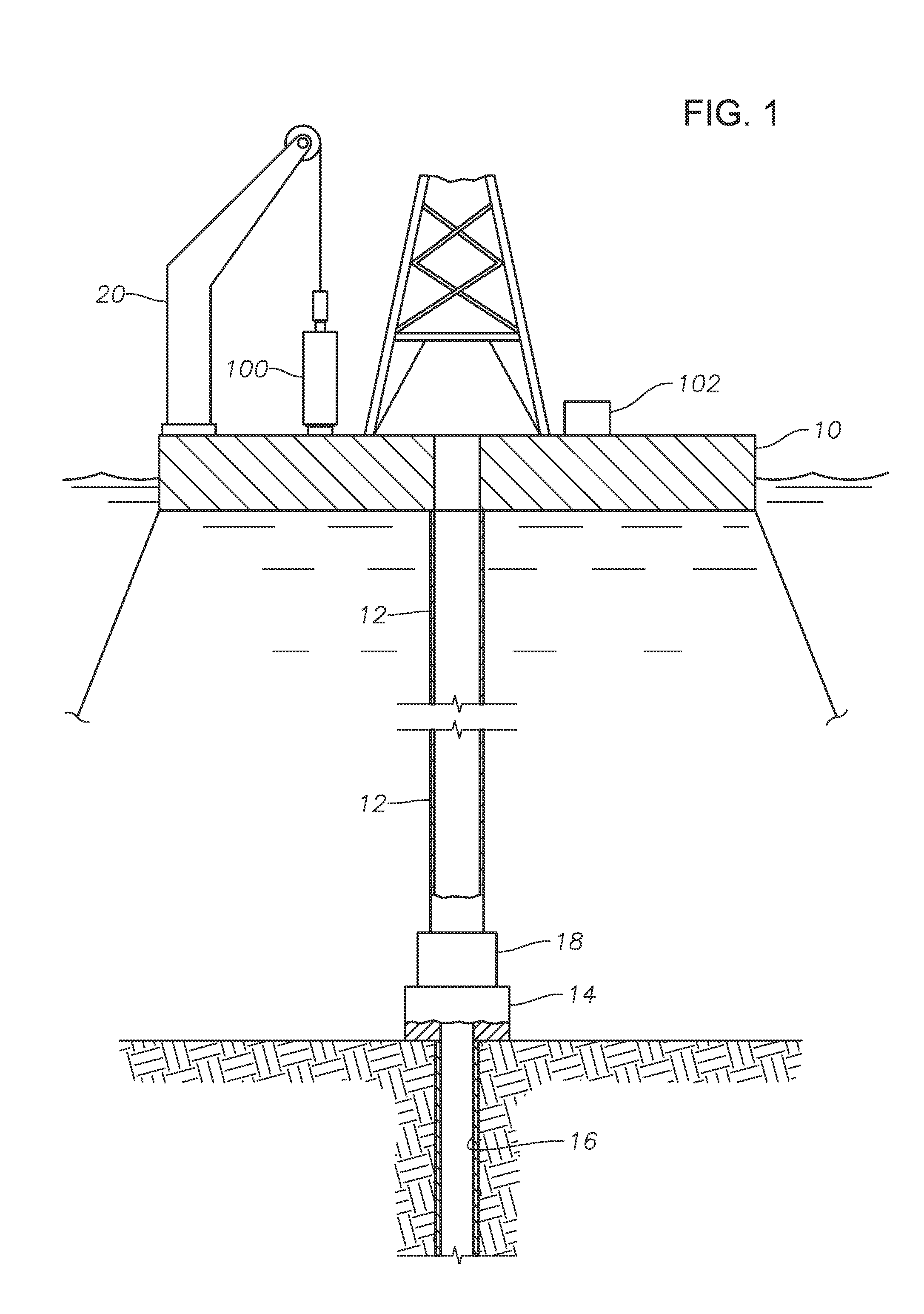
[0028]Referring to FIG. 1, a drilling platform 10 is shown. Drilling platform 10 is shown as a deepwater drilling platform, but can be any type of sea or land drilling platform or rig. Riser 12 extends from drilling platform 10 through the sea to subsea wellhead housing 14. Wellhead housing 14 is connected to wellbore 16. Blowout preventer (“BOP”) 18 is used to selective...


PUM


Abstract

A method and apparatus for setting an inner wellhead member in a subsea wellhead housing includes connecting an inner wellhead member to a running tool and running the running tool and wellhead member through a tubular member to a wellhead housing. A plurality of pistons urge fluid through a closed-loop hydraulic system. That fluid actuates a locking mechanism to lock the inner wellhead member into the wellhead housing, and also actuates a release mechanism to release the running tool from the inner wellhead member. The pistons are moved from one position to another in response to fluid pressure from the running string to which the running tool is connected, fluid pressure from the tubular member in which the running tool is located, or in response to fluid in the closed-loop hydraulic system that is being moved in response to the other one of the pistons.

Description

BACKGROUND OF THE INVENTION[0001]1. Field of the Invention[0002]The present invention relates in general to mineral recovery wells, and in particular to a running tool for running a wellbore tool through a tubular member.[0003]2. Brief Description of Related Art[0004]Running tools are used to run wellbore members, such as tubing hangers or internal tree caps, through a tubular member to the desired landing location. For example, a running tool can be used to run a tubing hanger from a drilling platform, through a riser, to a subsea wellhead housing. When the wellbore member is landed, the running tool must be actuated to release latch the wellbore member in place, and then the running tool must be disconnected from the now-set wellbore member. Control mechanisms to actuate the running tool can be problematic or time consuming. For example, hydraulic lines can be deployed through the riser to the running tool, or sometimes by way of a dart connected to the running tool, but the hydra...

Claims


Application Information

Patent Timeline
Patent Type & Authority Applications(United States)
IPC IPC(8): E21B23/00
CPCE21B33/04E21B23/04E21B33/043E21B23/00E21B23/042
Inventor FENWICK, RODNEY M.
Owner VETCO GRAY
Why Eureka
Try Eureka