

Systems and methods of power conversion for electrostatic precipitators
- Summary
- Abstract
- Description
- Claims
- Application Information
AI Technical Summary
Benefits of technology
Problems solved by technology
Method used
Image


Examples
Embodiment Construction
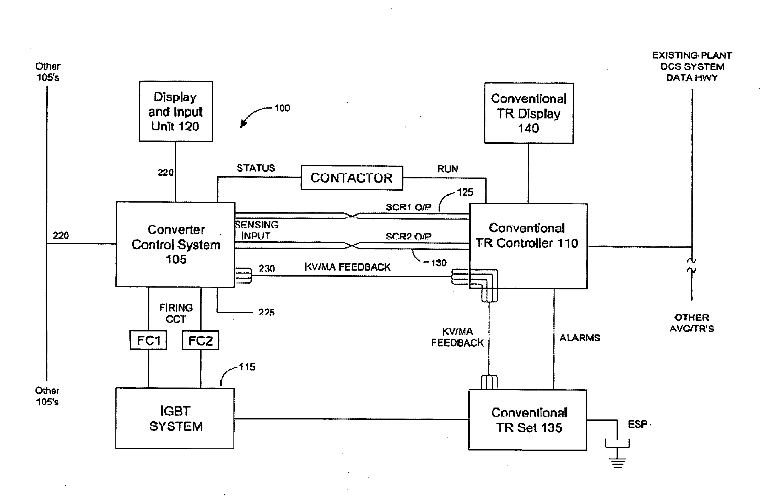
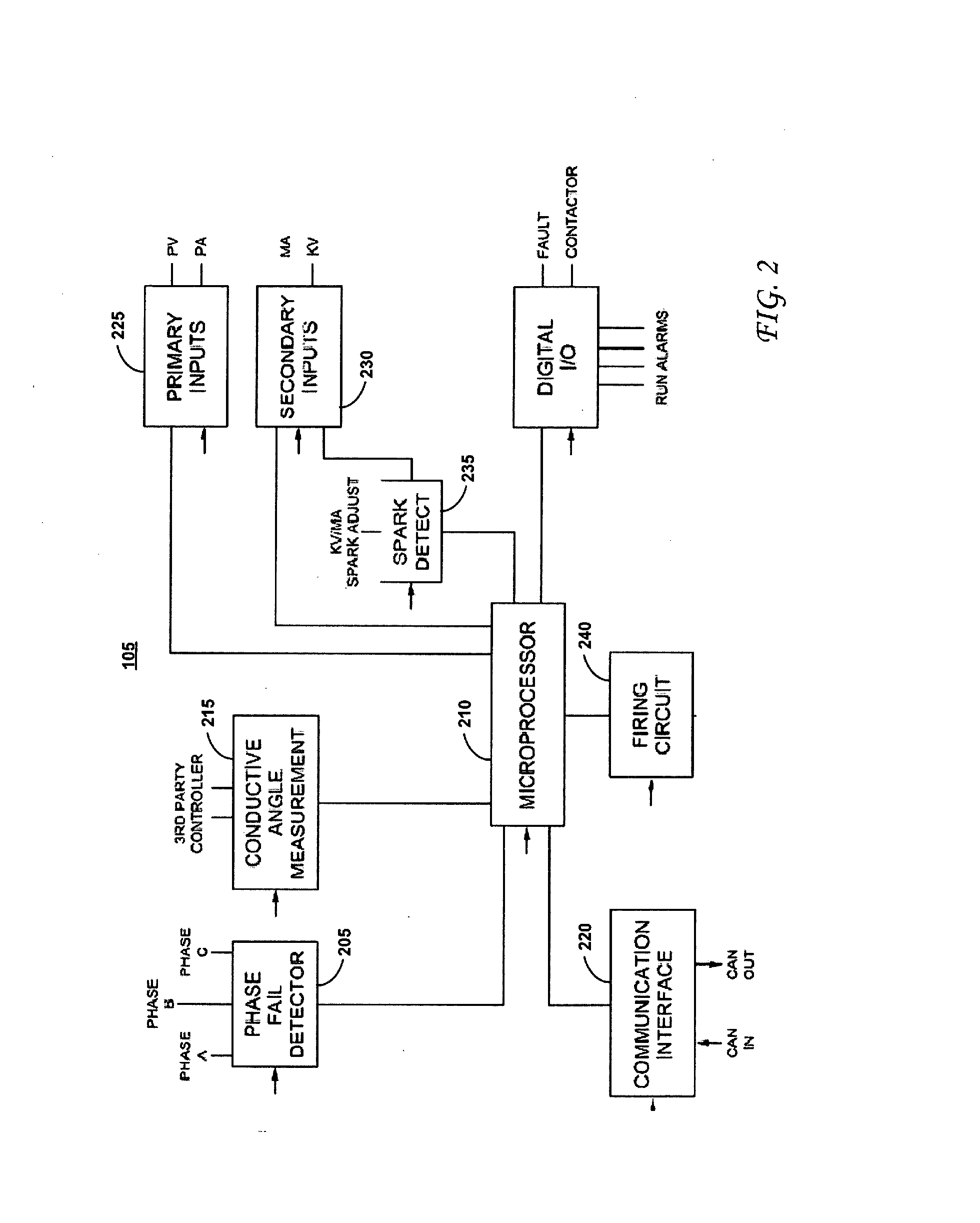
[0022]In the following description, numerous specific details are set forth. However, it is to be understood that implementations of the disclosed technology may be practiced without these specific details. In other instances, well-known methods, structures and techniques have not been shown in detail in order not to obscure an understanding of this description. References to “one implementation,”“an implementation,”“example implementation,”“various implementations,”“example embodiment,” etc., indicate that the implementation(s) of the disclosed technology so described may include a particular feature, structure, or characteristic, but not every implementation necessarily includes the particular feature, structure, or characteristic. Further, repeated use of the phrase “in one implementation” does not necessarily refer to the same implementation, although it may.
[0023]To facilitate an understanding of the principles and features of the disclosed technology, example embodiments are e...
PUM
 Abstract
Description
Claims
Application Information