X-ray ct system

a technology of ct system and x-ray, applied in the field of x-ray ct system, can solve the problems of difficulty for the examiner to distinguish between real differences and artifacts that have appeared in the differential image, and achieve the effect of reducing the waiting time for shuttle scanning

Active Publication Date: 2014-06-19
TOSHIBA MEDICAL SYST CORP
View PDF3 Cites 15 Cited by
  • Summary
  • Abstract
  • Description
  • Claims
  • Application Information

AI Technical Summary

Benefits of technology

[0015]The present embodiment is to solve the above-mentioned problem, and its objective

Problems solved by technology

If the difference shown in the differential image is extremely small or is a little different in luminance from the part other than the diffe

Method used


Image

  • X-ray ct system
  • X-ray ct system
  • X-ray ct system

Examples


Embodiment Construction

[0023]An embodiment of X-ray CT system is described with reference to each of the drawings.

[Configuration]

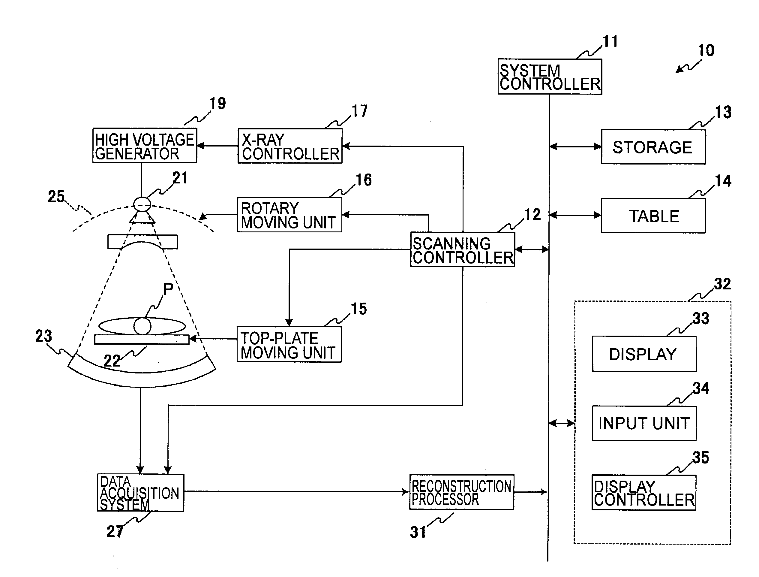
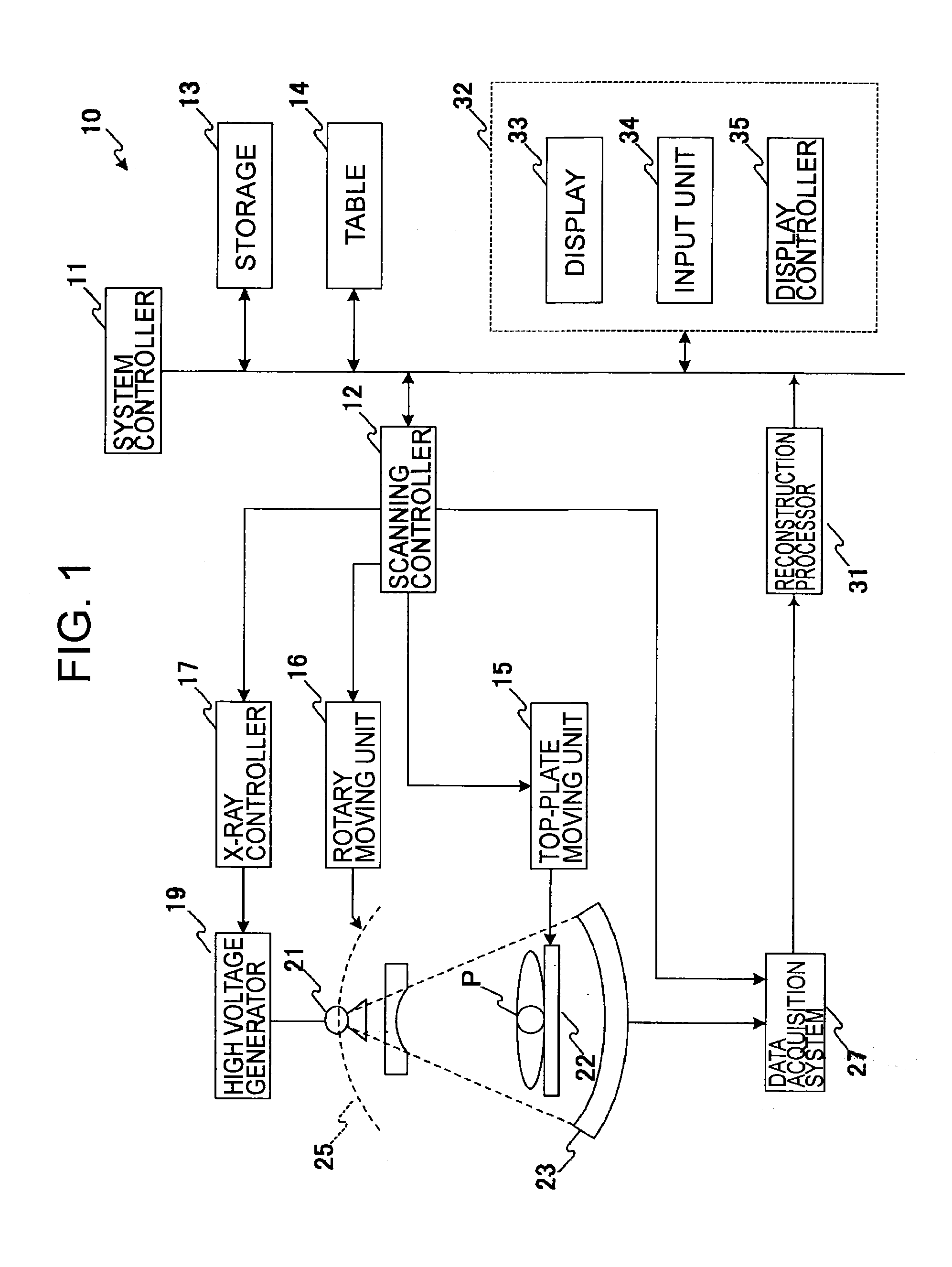
[0024]The configuration of the X-ray CT system is briefly explained in reference to FIG. 1, which is a block diagram showing the configuration of the X-ray CT system.

[0025]The X-ray CT system 10 comprises a system controller 11, a scanning controller 12, a storage 13, a table 14, a top-plate moving unit 15, a rotary moving unit 16, an X-ray controller 17, a high voltage generator 19, an X-ray radiator 21, a top plate 22, an X-ray detector 23, a rotary mechanism 25, a data acquisition system 27, a reconstruction processor 31, and an interface 32.

[0026]The system controller 11 comprises a central processing unit (CPU), and so on, and the system controller 11 controls and unifies the scanning controller 12, the storage 13, the table 14, the reconstruction processor 31, and the interface 32. Incidentally, one of the system controller 11, the scanning controller 12, and the display c...


PUM


Abstract

X-ray CT system is provided that reduces waiting time for shuttle scanning, comprising: top-plate moving unit; rotary moving unit; data acquisition system; and control unit. Top-plate moving unit displaces top plate to reciprocate in a direction from a starting point to an ending point and in the direction from the ending point to the starting point. Rotary moving unit drives X-ray radiator radiating X-rays to revolve around the subject. Data acquisition system detects X-rays passed through the subject and to gather projection data. Controller controls at least top-plate moving unit so that, during a scanning with X-rays, while projection data are gathered with reciprocating movement of top plate between the starting point and the ending point and with X-ray radiator being driven to make revolving movement, the duration required for reciprocation of the top plate movement being an integral multiple of revolution period of the revolving movement of X-ray radiator.

Description

TECHNICAL FIELD[0001]Embodiments according to the present invention relate to X-ray CT systems.BACKGROUND ART[0002]X-ray CT systems irradiate the subject with X-rays and acquire image data (hereinafter referred to merely as “data”) that represent a view in a predetermined sectional plane of the subject, on the basis of the X-rays that have passed through the subject.[0003]An example of a method of X-ray irradiation is involved in shuttle scanning, where the X-ray CT system performs scanning while the top plate with the subject is being reciprocated between the starting point and the ending point of a set scanning range (e.g., patent reference 1).[0004]There is a case where a scanning duration is set for the X-ray CT system, where the scanning duration is a time that the top plate takes to make a reciprocating movement in connection with X-ray irradiation. The scanning duration includes an acceleration time, a constant-speed time, and a deceleration time, along with a waiting time (i...

Claims


Application Information

Patent Timeline
IPC IPC(8): A61B6/03
CPCA61B6/035A61B6/032A61B6/0487A61B6/06A61B6/54
Inventor NAKANISHI, SATORUSUZUKI, TASURO
Owner TOSHIBA MEDICAL SYST CORP
Why Eureka
Try Eureka