Direct-drive wind turbine

a direct-drive, wind turbine technology, applied in the direction of machines/engines, liquid fuel engines, gearing, etc., can solve the problems of difficult exchange, large cylindrical bearing surface pads, heavy weight, etc., and achieve the effect of saving energy used for pump operation

Active Publication Date: 2014-06-19
SIEMENS GAMESA RENEWABLE ENERGY AS
View PDF2 Cites 17 Cited by
  • Summary
  • Abstract
  • Description
  • Claims
  • Application Information

AI Technical Summary

Benefits of technology

[0021]In at least one embodiment, the bearing is a hybrid bearing, where a lubrication film at the sliding surface is maintained by a combination of an applied pressure of an external pump and by rotating bearing parts. The pump is only needed when the wind turbine is starting or stopping rotation and the lubrication film cannot be ensured just by the rotation of the drive train. Thus, the lubrication is maintained independently of the rotation of the drive train. In addition, the energy used to operate the pump can be saved when rotation of the drive train is maintaining the lubrication film and the pump are not needed.

Problems solved by technology

As a consequence, the pads used for the cylindrical bearing surface are very large, heavy and difficult to exchange.

Method used


Image

  • Direct-drive wind turbine
  • Direct-drive wind turbine
  • Direct-drive wind turbine

Examples


Embodiment Construction

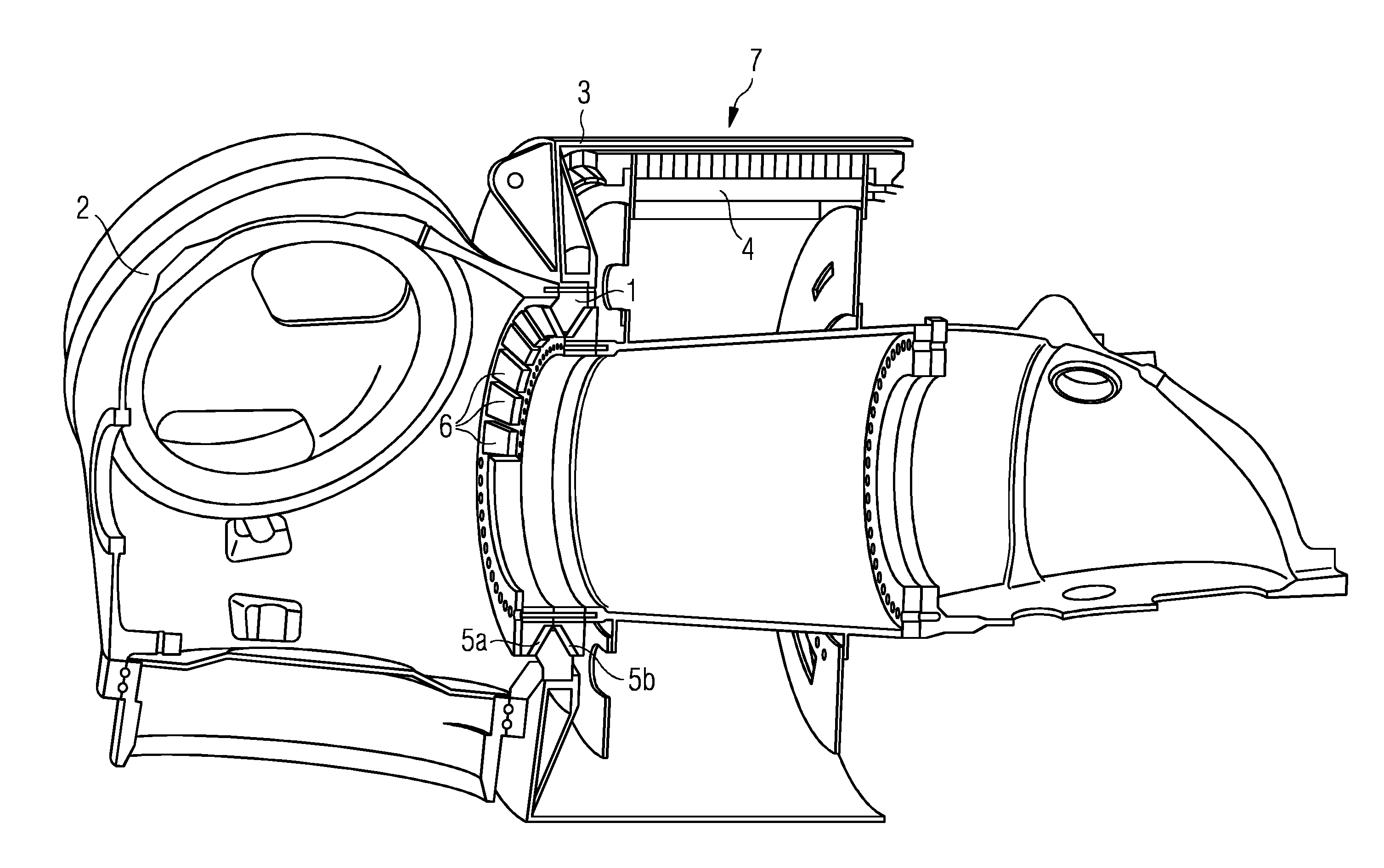
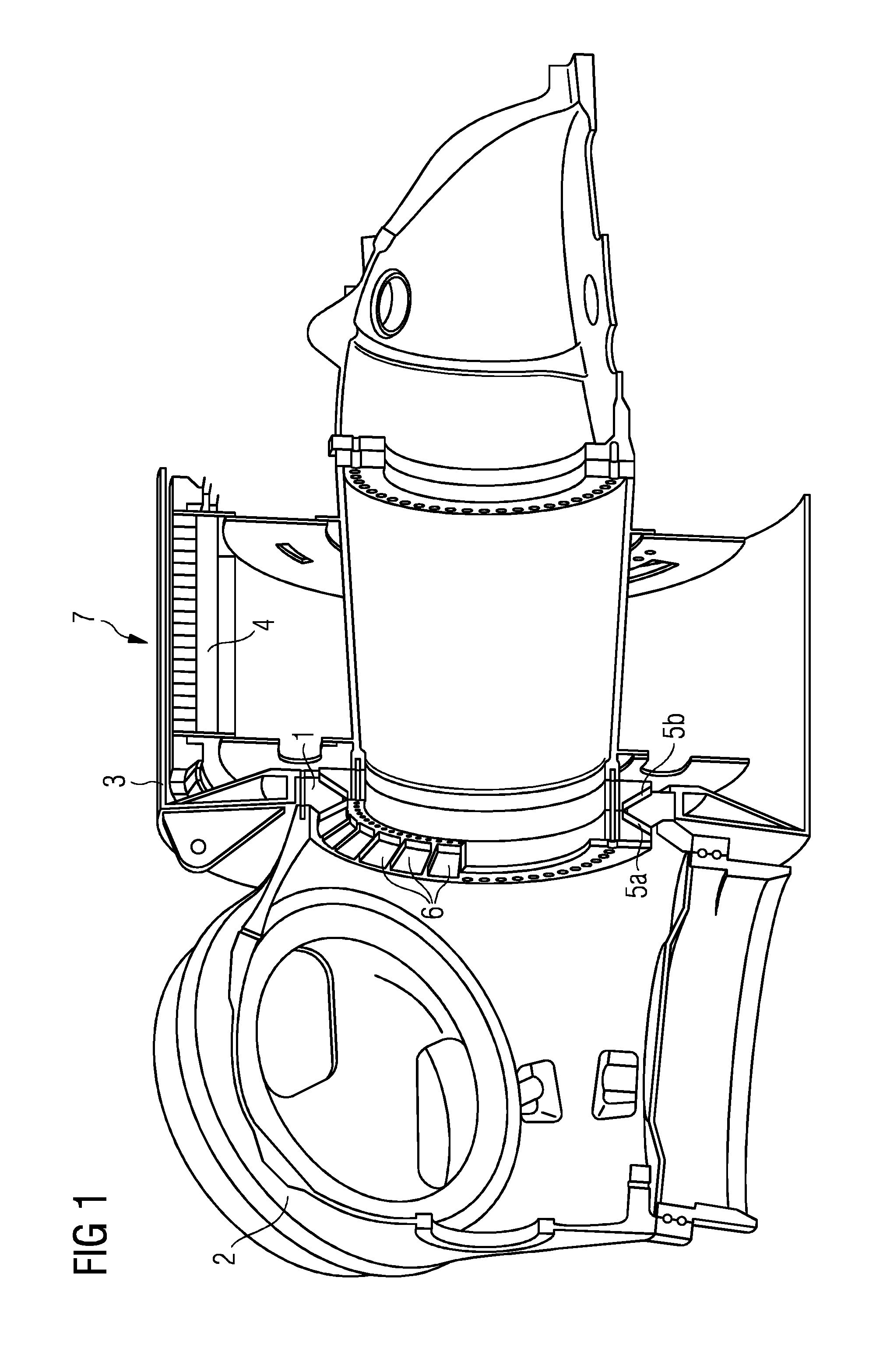
[0028]FIG. 1 shows a wind turbine with a plain bearing. FIG. 1 shows a longitudinal cut through the hub 2, the plain bearing 1, and the electrical generator 7 of a direct driven wind turbine. The longitudinal cut is going along the axis of rotation of the electrical generator 7 of the wind turbine. The hub 2 is connected to the rotor 3 of the generator and to the rotating side of the bearing 1. The stator 4 of the generator 7 is connected to the stationary side of the plain bearing 1.

[0029]The plain bearing 1 is located between the hub 2 of the wind turbine and the electrical generator 7 of the wind turbine. So it is connected with the stationary side to the hub-sided end of the stator 4 of the generator 7 and with the rotating side to the hub 2 of the wind turbine. The plain bearing 1 is a tapered bearing. The cut through the bearing shows a V-shaped arrangement of two sliding surfaces 5a and 5b, which are tilted and arranged in a way that they are reversely sloped in axial directi...


PUM


Abstract

A direct driven wind turbine and a main bearing used in such a wind turbine is provided. A rotor of the wind turbine is directly connected with a rotating drive train of the wind turbine, the rotating drive train is directly connected with a rotor of an electrical generator of the wind turbine. The rotating drive train is connected with a stationary part of the wind turbine via at least one bearing, which allows the rotation of the drive train in relation to the stationary part. The at least one bearing is a plain bearing and the bearing is a tapered bearing, which comprises at least one conical shaped sliding surface.

Description

FIELD OF TECHNOLOGY[0001]The following relates to a direct driven wind turbine and the main bearing used in such a wind turbine.BACKGROUND[0002]A wind turbine transfers the energy of moving air into electrical energy. The moving air accelerates the rotor of the wind turbine. The rotation of the rotor is transferred to an electrical generator. The electrical generator transforms the rotational energy into electrical energy. In the last years the concept of a direct driven wind turbine was established. In a direct driven wind turbine, the rotational energy of the rotor is transferred to the generator directly without the use of a gearbox. In a direct driven wind turbine the rotor of the wind turbine is directly connected to the rotor of the electrical generator. The chain of mechanically connected parts leading from the rotor of the wind turbine to the rotor of the generator is called the drive train of the wind turbine.[0003]To allow the rotational movement and to provide the necessa...

Claims


Application Information

Patent Timeline
Patent Type & Authority Applications(United States)
IPC IPC(8): F03D9/00
CPCF03D9/002F16C17/10F05B2220/7066F16C17/03F16C17/06F03D80/70F03D15/00F03D9/25F16C2360/31F05B2240/50F05B2260/40311Y02E10/72F16H57/021F16C19/364F16H57/082F16C19/386F16H1/2836F16C2361/61F16C2300/14F03D15/20
Inventor PEDERSEN, BOTHOMSEN, KIM
Owner SIEMENS GAMESA RENEWABLE ENERGY AS
Why Eureka
Try Eureka