Direct orientation vector rotor

a rotor and vector technology, applied in the field of direct operation of rotary wing aircraft, can solve the problems of stalling, decrease in total lift, unbalanced relative flow of air passing over the rotor disk during flight, etc., and achieve the effect of simple and fast rotor speed

Active Publication Date: 2014-06-19
CARREKER RAYMOND GEORGE
View PDF3 Cites 8 Cited by
  • Summary
  • Abstract
  • Description
  • Claims
  • Application Information

AI Technical Summary

Benefits of technology

[0004]In one embodiment, a DOVER includes an articulated rigid mast assembly by which the rotor can be pointed at a more oblique angle into the relative wind resulting in a system in which the motion is translational in the direction of the driving force. The complex mechanism for cyclic pitch control of the rotor blades can be dispensed by in one embodiment allowing for a simpler and more lightly configured rotor, while retaining the flapping and lead-lag attributes. Since the problem of retreating blade stall is largely reduced or eliminated, shorter blades and faster rotor speeds are possible allowing the DOVER to combine the function and utility of the helicopter rotor with the speed and reliability of the propeller of a fixed-wing or tilt-rotor aircraft, possibly leading the path toward the implementation of supersonic blade tip technology. In contrast to tilt-rotor technology which involves the cumbersome rotation of the total drive train in a slow inline arc, the DOVER allows the engine and transmission to remain in situ while the rotor and attached driven shaft or mast can freely and rapidly translate in any orientation required to control the aircraft thereby retaining the utility for which the rotorcraft is designed. In one embodiment, the articulated rigid mast assembly is actuated by a ball-face spline-tooth gear coupling, one as component of the drive train and the other as component to the driven rotor slave. In another embodiment, the output gear is in mesh with the input gear as the former is able to rotate, pivot, and swivel with respect to the latter thereby shifting the load contact area or active profile. In another embodiment, an inclination apparatus consists of a hingeably attached sleeve which sets the orientation of the rotor mast whereby said sleeve is levered along an inclination traverse being connected at arc perimeter to a thrust and vibration conductor that is powered along said inclination traverse on a transfer track by a linear motion actuator. In yet another embodiment, the inclination mechanism is housed within a turret which serves as a mass damper housing for said mechanism while allowing rapid 360° azimuth rotation of the total mechanism by way of a thrust bearing-configured ring unit that ultimately supports the in-flight mass of the aircraft. In another embodiment, the gear mesh is lubricated by a closed motion-adapted spray system. The apparatus described herein embodies a method of point-origin vector divergence thrust for controlled flight.

Problems solved by technology

An inherent instability is manifest within the rotor blades because they are manipulated from the fixed axis of the hub, with said instability ultimately being transferred to the flight dynamics of the aircraft.
Since the tip path plane remains relatively parallel to the relative wind (also called the relative air flow), the rotating blades exhibit drastic lift variance as they advance and retreat within the relative wind thereby causing an unbalanced relative flow of air passing over the rotor disk during flight.
This uneven allocation of airflow over the total rotor disk produces a dissymmetry of lift leading to a decrease in total lift and a possible stall, a condition that is amplified at higher air speeds and which subsequently limits the potential flight speed obtainable.

Method used


Image

  • Direct orientation vector rotor
  • Direct orientation vector rotor
  • Direct orientation vector rotor

Examples


Embodiment Construction

[0030]Overview:

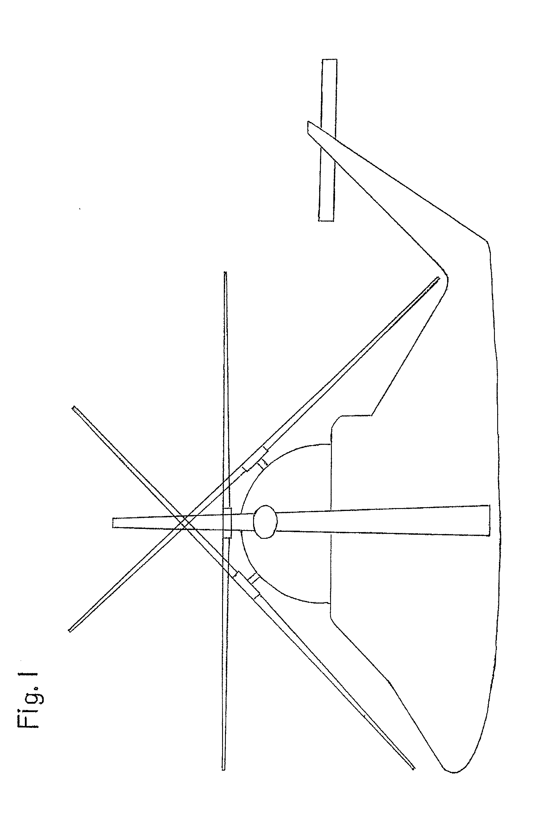
[0031]In FIG. 1, a DOVER system is shown displaying a 360° freedom of movement of operation of the rotor as delineated by an inclination of 45° at forward, aft, and lateral positions from the horizontal on a traditional tail rotor design helicopter, although the DOVER also is applicable to fenestron shrouded tail rotor and No Tail Rotor (NOTAR) blown-air designs. In alternatives, the total possible degree of inclination from the horizontal may vary depending on the configuration of the helicopter, in order to prevent the rotor from hitting the helicopter fuselage. In addition to the DOVER system being oriented to assist in landing operations, providing various orientations of the rotor may also provide for increased performance in terms of the speed and maneuverability of the aircraft including tighter and higher velocity cornering and the static orientation of the aircraft to enable weapon systems operations or other types of operations where the position of the airc...


PUM


Abstract

A direct orientation vector rotor (DOVER) for use on rotary wing aircraft includes a gear set for multidirectional rotor orientation based on the spherical coordinate system; an inclination mechanism, wherein the rotor is moved from the 0° horizontal position to an inclined position; a rotational turret, wherein the rotor is moved along the azimuth and wherein the inclination mechanism is housed; and a motion-adapted gear lubrication housing.

Description

BACKGROUND[0001]Embodiments of the DOVER relate to apparatuses used by the aerospace industry. More specifically, embodiments of the DOVER relate to the operation of rotary wing aircraft.DESCRIPTION OF THE RELATED ART[0002]Any discussion of the prior art throughout the specification should in no way be considered an admission that such art is widely known or forms part of common knowledge in the field.[0003]The rotary wing aircraft, and more specifically the helicopter, is generally known as a utility vehicle distinguished by its ability to hover, fly vertically, and fly in various directions regardless of azimuthal orientation. Helicopters achieve directional flight by converting the vertical lift component produced by the rotating blades into a horizontal thrust component by changing the pitch of each individual blade as it revolves in its orbit around the hub onto which it is attached. The collective blade assembly or rotor disk consequently is tilted into a vector called the tip...

Claims


Application Information

Patent Timeline
Patent Type & Authority Applications(United States)
IPC IPC(8): B64C27/52F16D3/18
CPCB64C27/52F16D3/18F16D3/185B63H5/125B64C27/28
Inventor CARREKER, RAYMOND GEORGE
Owner CARREKER RAYMOND GEORGE
Why Eureka
Try Eureka