Lubrication device of power transmission device for hybrid vehicle

a technology of hybrid vehicles and lubrication devices, which is applied in the direction of electric devices, propulsion by batteries/cells, transportation and packaging, etc., can solve the problems of increasing agitation loss and supply of oil that is not considered appropriate for cooling an electric motor, so as to prevent excessive reduce the agitation resistance of the gear member due to oil viscosity, and reduce the effect of excess oil supply to the gear member

Inactive Publication Date: 2014-06-26
TOYOTA JIDOSHA KK
View PDF2 Cites 34 Cited by
  • Summary
  • Abstract
  • Description
  • Claims
  • Application Information

AI Technical Summary

Benefits of technology

[0008]Consequently, oil forcibly transferred from the oil pump is preferentially supplied through the first pipe to the second electric motor. On the other hand, the first electric motor is supplied with oil accumulated in the first catch tank through the second pipe. Since oil is accumulated in the first catch tank earlier than the second catch tank, the accumulated oil is quickly supplied to the second pipe. Therefore, even while a smaller amount of oil is supplied for example, even during a low vehicle speed etc., the oil supplied to the first electric motor can quickly be ensured. Although a higher vehicle speed increases amounts of oil forcibly transferred from the oil pump, since the oil flows down from the oil flow outlet of the first catch tank and is accumulated in the second catch tank, the excessive oil supply to the gear member is reduced and the agitation resistance of the gear member due to oil viscosity is reduced. As described above, oil can be supplied to the first electric motor, the second electric motor, and the gear member in appropriate distribution. Since oil forcibly transferred by the oil pump is supplied to the first electric motor and the second electric motor, high-temperature oil is prevented from being supplied to the first electric motor and the second electric motor.
[0009]Preferably, the second catch tank is disposed with a lubrication oil supply hole for supplying oil to the gear member, and the lubrication oil supply hole is disposed at a position supplied with oil when an accumulation amount of oil in the second catch tank exceeds a preset amount. Consequently, since the preset amount of oil is accumulated in the second catch tank, excessive oil supply to the gear member is prevented even during high speed running and an appropriate amount of oil can be supplied to the gear member.
[0010]Preferably, the second catch tank has a dividing wall formed for dividing into an oil accumulating portion accumulating oil and a space disposed with the lubrication oil supply hole, and when a height of an oil surface of the oil accumulating portion exceeds an upper end portion of the dividing wall, oil is supplied to the lubrication oil supply hole. Consequently, the configuration of supplying an appropriate amount of oil to the gear members is easily provided by adjusting the position of the upper end portion of the dividing wall.
[0011]Preferably, the first pipe is extended to a position vertically above the second electric motor, and the second pipe is extended to a position vertically above the first electric motor. Consequently, oil can efficiently be supplied to the first electric motor and the second electric motor.
[0012]Preferably, the oil passage is disposed in the vicinity of an oil flow inlet of the second pipe in series, and a restrictor is formed in the oil passage. Consequently, the oil outflowing from the oil passage efficiently flows into the oil flow inlet of the second pipe.
[0013]Preferably, the oil forcibly transmitted from the oil pump is supplied through a third pipe disposed outside the transaxle case to the first pipe. Consequently, the oil is cooled when passing through the third pipe and the cooled oil can be supplied to the first pipe.

Problems solved by technology

Excessive oil supply to the gear member causes a problem of an increase in agitation loss due to oil viscosity.
The oil scraped up by the gears is at a high temperature and, even though the temperature is somewhat lowered by mixing with low-temperature oil supplied from the oil pump 20 in the catch tank 52, this causes a problem of supply of oil that is not considered appropriate for cooling an electric motor.

Method used


Image

  • Lubrication device of power transmission device for hybrid vehicle
  • Lubrication device of power transmission device for hybrid vehicle
  • Lubrication device of power transmission device for hybrid vehicle

Examples


example

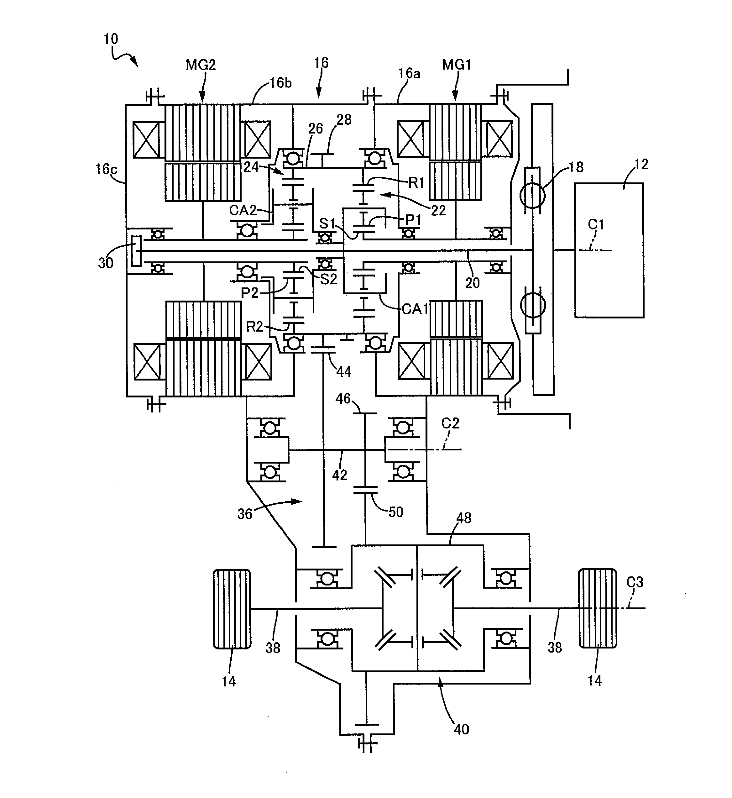
[0022]FIG. 1 is a schematic for explaining a configuration of a hybrid vehicle power transmission device 10 (hereinafter, a power transmission device 10) of an example of the present invention. In FIG. 1, the vehicle power transmission device 10 is disposed between an engine 12 and drive wheels 14 in an FF (front-engine front-drive) type hybrid vehicle, for example. The vehicle power transmission device 10 includes in a transaxle case 16 an input shaft 20 coupled via a damper device 18 to an output shaft (crank shaft) of the engine 12, as well as a first electric motor MG1, a power distribution planetary gear device 22, a deceleration planetary gear device 24, and a second electric motor MG2 arranged concentrically with the input shaft 20 in this order from the side of the damper device 18. The damper device 18, the input shaft 20, the first electric motor MG1, the power distribution planetary gear device 22, the deceleration planetary gear device 24, and the second electric motor M...


PUM


Abstract

A lubrication device for a hybrid vehicle power transmission device including a gear member, a first electric motor, and a second electric motor within a transaxle case, the lubrication device includes: a first pipe supplying oil forcibly transferred from an oil pump to the second electric motor; an oil passage branched from the first pipe; a first catch tank supplied with oil from the oil passage; a second pipe connected to the first catch tank to supply oil accumulated in the first catch tank to the first electric motor; an oil flow outlet disposed in the first catch tank and located above the second pipe; and a second catch tank disposed vertically beneath the first catch tank to receive oil outflowing from the oil flow outlet.

Description

TECHNICAL FIELD[0001]This is a Continuation-in-Part of International Application No. PCT / JP2011 / 066364 filed Jul. 19, 2011. The disclosure of the prior application is hereby incorporated by reference herein in its entirety.[0002]The present invention relates to a lubrication device of a power transmission device included in a hybrid vehicle and particularly to a structure of a lubrication device capable of supplying oil to an electric motor and a gear member in proper distribution.BACKGROUND ART[0003]A power transmission device of a hybrid vehicle including an electric motor inside a case is disposed with a lubrication device for supplying oil to the electric motor and a gear member requiring lubrication. A heating part cooling structure for a vehicle drive device described in Patent Document 1 is an example thereof. The heating part cooling structure of Patent Document 1 is disposed with a catch tank 52, a first oil passage 61 for supplying oil to a first generator motor 13, and a ...

Claims


Application Information

Patent Timeline
Patent Type & Authority Applications(United States)
IPC IPC(8): F16H57/04
CPCF16H57/0436B60K6/365B60K6/445F16H57/045F16H57/0476H02K9/19H02K16/00H02K7/116F16H57/0482Y02T10/62B60L3/0061B60L15/2054B60L2240/12B60L2240/36Y02T10/72B60L50/61B60L50/16Y02T10/64Y02T10/7072Y02T10/70
Inventor TAKAGI, KIYONORIKIMURA, HIROAKITOMITA, MAKOTOTSUKIASHI, NORIHIDE
Owner TOYOTA JIDOSHA KK
Why Eureka
Try Eureka