Eureka AIR delivers breakthrough ideas for toughest innovation challenges, trusted by R&D personnel around the world.

Shock absorbing member

Active Publication Date: 2014-06-26
NIPPON STEEL CORP
View PDF5 Cites 7 Cited by
  • Summary
  • Abstract
  • Description
  • Claims
  • Application Information

AI Technical Summary

Benefits of technology

The present invention provides a shock absorbing member that can effectively absorb impact energy by inducing a concave-convex independent mode. This results in improved shock-absorbing performance.

Problems solved by technology

However, when the plate thickness of the above shock absorbing member is increased, the weight of the member is increased, whereby the weight of a chassis including the shock absorbing member is also increased.
As a result, fuel efficiency and driving performance of a motorcar are deteriorated.
Therefore, the formability of a high-strength steel plate is not good, and thus there are limitations to increasing the strength of a steel plate for the shock absorbing member at present.
Further, a risk of injury to driver and a passenger is increased, since a portion which is not to be deformed is buckled; it is difficult to keep a survival space for the drive and the passenger due to the deformation of the cabin; or a significant change of acceleration is applied to the driver and the passenger.
However, there is no firm theory for determining the above arrangement of the beads, and at present, the arrangement is determined by repeatedly buckling test or a computer simulation regarding the shock absorbing member.
Accordingly, it is necessary to repeatedly carry out the above test or simulation in relation to each kind of chassis, whereby design efficiency is deteriorated.
Moreover, since various load conditions or buckling modes predicted when actual collision cannot be dealt with, it is very difficult to optimize the arrangement of the beads by using the above techniques.

Method used


Image

  • Shock absorbing member
  • Shock absorbing member
  • Shock absorbing member

Examples


working example 1

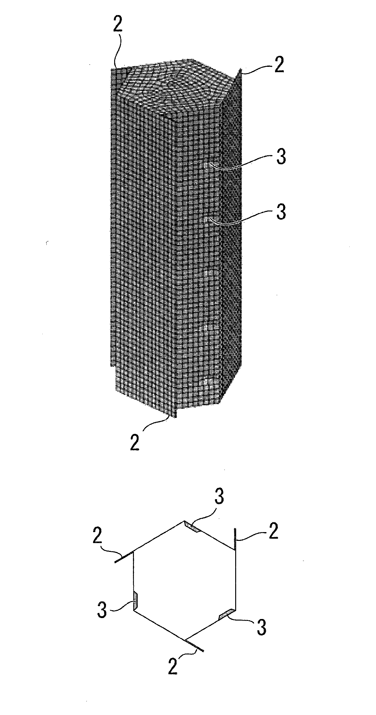
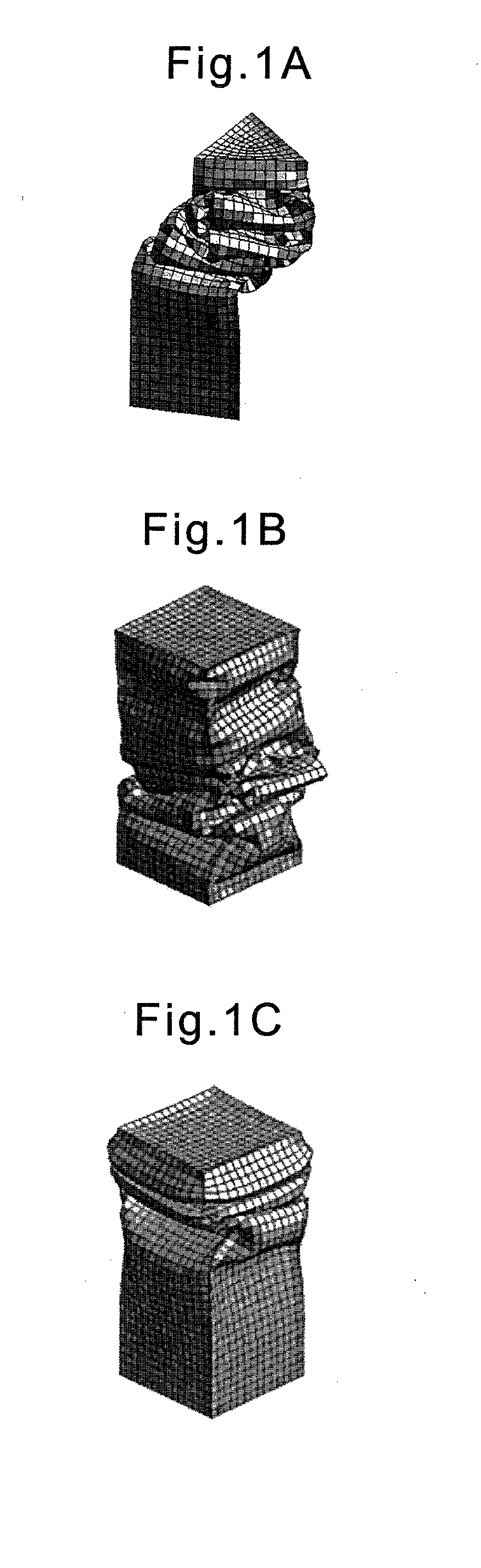
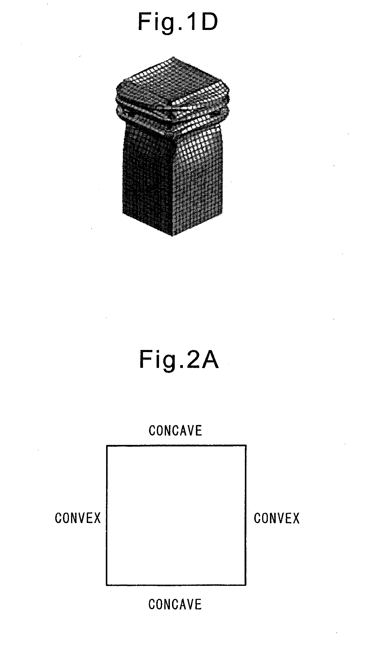
[0114]As shown in FIG. 9B, in working example 1, a flange was formed on each of two opposing corners of the hollow columnar member (a protruding length of each flange was 20 mm), so that the two flanges were directed in the same direction with respect to the circumferential direction. In this case, as shown in FIG. 11, the bucking of the member progressed in the concave-convex independent mode from initial stage of the buckling.

working example 2

[0115]As shown in FIG. 9C, in working example 2, in addition to the configuration of working example 1, dimples were formed on one of the neighboring walls sandwiching the corner on which the flange was not formed. Each dimple dented from an outer surface of the shock absorbing member, and was positioned so as to be deviated towards the corner, relative to the center of the wall, which was positioned on the side opposite to the direction of protrusion of the flange with respect to the circumferential direction. In this case, as shown in FIG. 12, the bucking of the member progressed in the concave-convex independent mode from initial stage of the buckling.

working example 3

[0116]As shown in FIG. 9E, in working example 3, in addition to the configuration of working example 2, dimples were formed on one of the neighboring walls sandwiching the corner on which the flange was formed. Each dimple dented from an outer surface of the shock absorbing member, and was positioned so as to be deviated towards the corner, relative to the center of the wall, which was positioned on the side opposite to the direction of protrusion of the flange with respect to the circumferential direction. In this case, as shown in FIG. 13, the bucking of the member progressed in the concave-convex independent mode from initial stage of the buckling.


PUM


Abstract

A hollow columnar shock absorbing member (1) has an axis (O), a plurality of rectangular walls (1a, 1b, 1c, 1d) extending parallel to axis (O), and a polygonal cross-section perpendicular to axis (O), the shock absorbing member extending in the direction of axis (O) and absorbing externally-applied impact energy while buckling in the direction of axis (O). Shock absorbing member (1) is provided with at least two flanges (2a, 2b, 2c, 2d) protruding from at least two edges (1e, 1f, 1g, 1h) formed by at least two sets of neighboring walls among a plurality of walls, and the at least two flanges are arranged so that the directions of protrusion of the flanges from the edges are directed to the same direction with respect to a circumferential direction.

Description

TECHNICAL FIELD [0001]The present invention relates to a shock absorbing member which absorbs externally-applied impact energy while buckling.BACKGROUND ART [0002]In recent years, in the automotive field, etc., improvement in fuel efficiency and motion performance have been sought, while improvement in collision safety has also been sought. As a chassis of a motorcar, in order to balance reduced weight and high stiffness, a chassis structure referred to as a “monocoque body,” wherein a frame and a body are integrally formed, is generally used. Further, in the chassis of a motorcar, in order to maintain a survival space for a driver and a passenger in a collision, a shock absorbing structure is generally used, wherein a space (for example, an engine room or a luggage room) other than a cabin is preferentially collapsed, so that impact load applied to the cabin is attenuated as much as possible and the deformation of the cabin is minimized.[0003]Therefore, in order to constitute a cha...

Claims


Application Information

Patent Timeline
IPC IPC(8): F16F7/12
CPCF16F7/12B62D21/152B62D21/15F16F7/123
Inventor HIROSE, SATOSHI
Owner NIPPON STEEL CORP
Why Eureka
Eureka Blog
Learn More