Synchronization of nanomechanical oscillators

a synchronization and nanomechanical technology, applied in the direction of oscillator generators, pulse automatic control, solids analysis using sonic/ultrasonic/infrasonic waves, etc., can solve the problems of reducing the advantages of the array, limited experimental studies on synchronized oscillators, etc., to reduce phase noise, excellent observation and control of parameters, and small footprint

Active Publication Date: 2014-06-26
CALIFORNIA INST OF TECH
View PDF7 Cites 166 Cited by
  • Summary
  • Abstract
  • Description
  • Claims
  • Application Information

AI Technical Summary

Benefits of technology

[0026]Advantages for at least some embodiment described herein include, for example, excellent observation and control of parameters governing the dynamics of synchronization; and/or possible large scale integration; and/or close quantitative agreement between experiment and theory; and/or significant reduction in the phase noise of the oscillators in the synchronized state; and/or high-quality factors; and/or sm

Problems solved by technology

Synchronization of oscillators is an important topic, but experiemental studies on synchronized oscillators are limited.

Method used


Image

  • Synchronization of nanomechanical oscillators
  • Synchronization of nanomechanical oscillators
  • Synchronization of nanomechanical oscillators

Examples


working examples

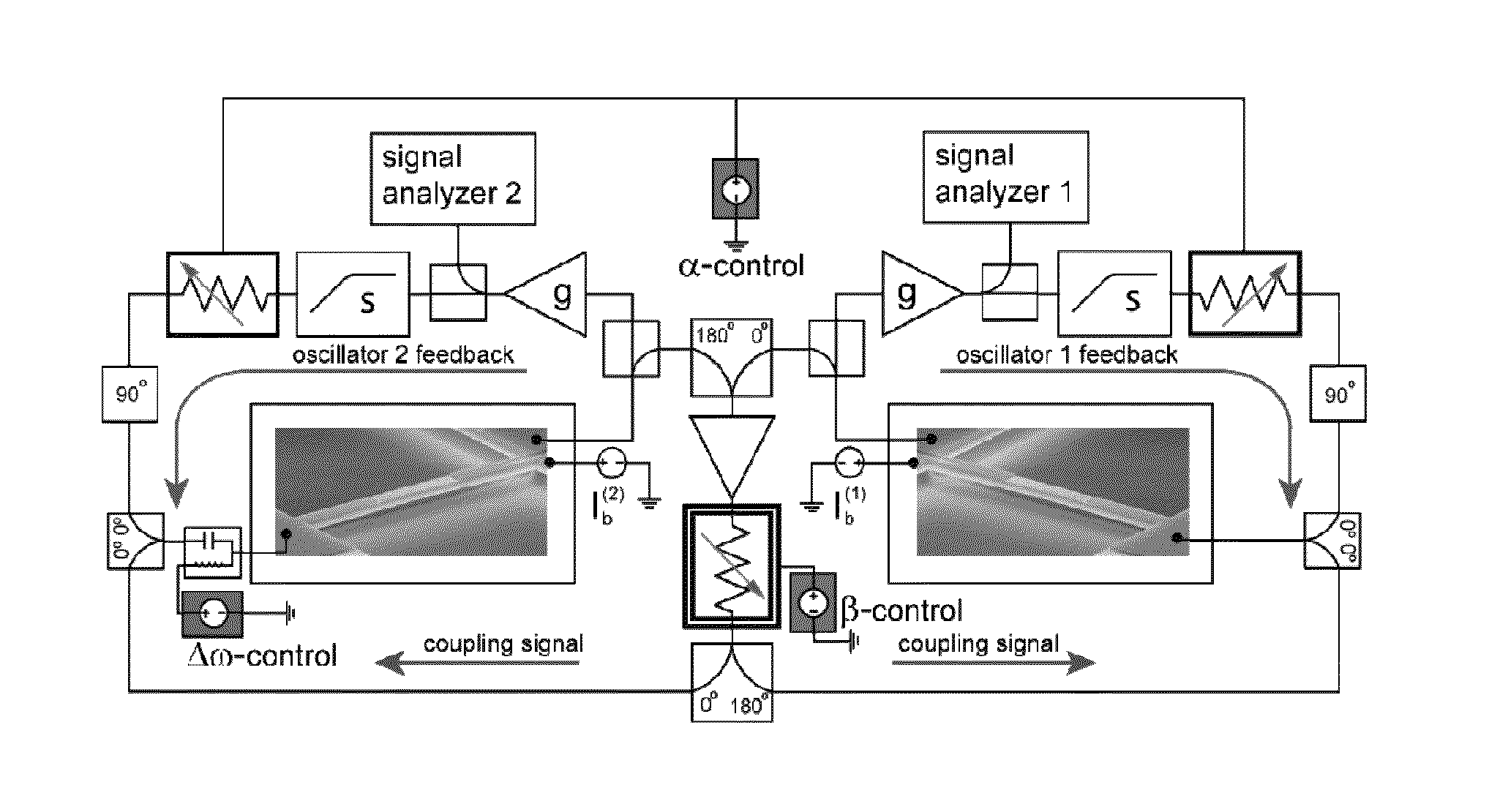
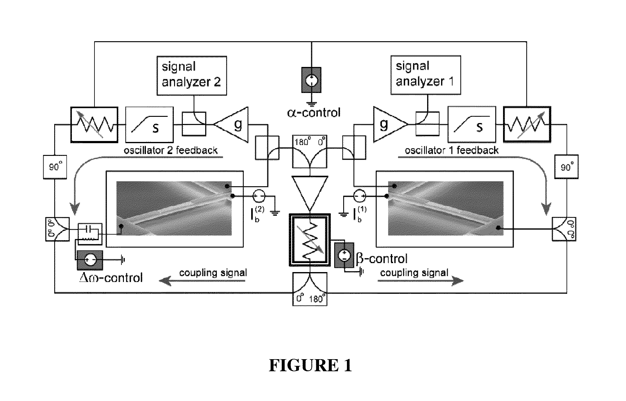
[0080]Experimental Methods: Device fabrication has been previously described by Villanueva et al23. All measurements were taken at a pressure of less than 100 mT through a balanced bridge technique (not pictured in the figure)29 in order to reduce the effect of parasitic capacitances24. All three synchronization parameters are modified by external and independent DC voltage sources. The coupling strength can be controlled by adjusting the feedback gain in the coupling loop. We amplify and tune (using the red DC control voltage box in FIG. 1) a voltage controlled attenuator (double-line box in FIG. 1) in order to modify this coupling feedback gain. The frequency difference between the two oscillators can be linearly controlled by inducing stress in one of the beams by a DC piezovoltage, as shown by the blue box in FIG. 1. The frequency pulling can be adjusted by varying the absolute oscillator amplitudes (keeping the relative amplitudes fixed to ensure that Equations 1-3 remain valid...

ring embodiment

[0181]For chains of oscillators connected as a ring (linear chains can be made into a ring by connecting the ends together), synchronized states of disconnected topologies may be found, namely with different integral winding numbers of the phase around the ring. In addition to the quasi-uniform state, in which the oscillators synchronize to roughly equal phases (with small phase differences to counteract the small frequency differences), splay states in which adjacent phases are rotated by about 2πn / N, with n the integral winding number, may also be exist. If there are reactive components to the coupling, these states will consist of waves of phase propagating around the ring. In FIG. 27, we show a simulation of a coupled oscillator ring with a total initial phase winding number of 1, which gives a wave propagating around the ring and smoothes out phase imperfections (FIG. 27a) even in the presence of dispersion (FIG. 27b). The topology of the ring remains constant while the propaga...


PUM


Abstract

Synchronization of oscillators based on anharmonic nanoelectromechanical resonators. Experimental implimentation allows for unprecedented observation and control of parameters governing the dynamics of synchronization. Close quantitative agreement is found between experimental data and theory describing reactively coupled Duffing resonators with fully saturated feedback gain. In the synchonized state, a significant reduction in the phase noise of the oscillators is demonstrated, which is key for applications such as sensors and clocks. Oscillator networks constructed from nanomechanical resonators form an important laboratory to commercialize and study synchronization—given their high-quality factors, small footprint, and ease of co-integration with modern electronic signal processing technologies. Networks can be made including one-, two-, and three-dimensional networks. Triangular and square lattices can be made.

Description

RELATED APPLICATIONS[0001]The application claims priority to US provisional filing Ser. No. 61 / 719,205 filed Oct. 26, 2012, which is hereby incorporated by reference in its entirety.FEDERAL FUNDING STATEMENT[0002]This invention was made with government support under FA8650-10-1-7029 awarded by the USAF / ESC. The government has certain rights in the invention.INTRODUCTION[0003]Synchronization is a ubiquitous phenomenon both in the physical and the biological sciences. Synchronization of oscillators is an important topic, but experiemental studies on synchronized oscillators are limited. Synchronization also has many important commercial implications including for the commercialization of nanotechnology systems.[0004]For example, nanomechanical systems can be improved through synchronization. To illustrate, NEMS oscillators have been exploited for a variety of applications, but arrays of these NEMS oscillators can suffer from statistical deviations. Arrays having large numbers of oscil...

Claims


Application Information

Patent Timeline
IPC IPC(8): H03L7/00
CPCH03L7/00G01N29/11H03B5/30
Inventor MATHENY, MATTHEWROUKES, MICHAEL L.CROSS, MICHAEL C.VILLANUEVA TORRIJO, LUIS GUILLERMOKARABALIN, RASSUL
Owner CALIFORNIA INST OF TECH
Why Eureka
Try Eureka