DC offset cancellation for a multi-stage amplifier

a multi-stage amplifier and dc offset technology, which is applied in the direction of dc-amplifiers with dc-coupled stages, differential amplifiers, and amplifiers with semiconductor devices/discharge tubes, etc., can solve the problem of amplifier saturation, the presence of dc offset is typically a problem, and the possibility of amplifier saturation, so as to reduce the residual dc offset and reduce the inherent dc offset

Inactive Publication Date: 2014-06-26
HONG KONG APPLIED SCI & TECH RES INST
View PDF3 Cites 18 Cited by
  • Summary
  • Abstract
  • Description
  • Claims
  • Application Information

AI Technical Summary

Benefits of technology

[0008]A multi-stage amplifier incorporating DC offset cancellation for reducing a residual DC offset at the output of the amplifier is provided. The multi-stage amplifier has a plurality of series-connected gain stages each of which comprises a differential amplifier unit configured to generate a pair of differential outputs from a pair of differential inputs. In particular, a trailing stage in the plurality of series-connected gain stages comprises a digital DC offset cancellation module configured to compensate for a DC offset of the trailing stage's differential amplifier unit. Furthermore, the digital DC offset cancellation module comprises a comparator coupled to the pair of differential outputs of the trailing stage's differential amplifier unit for receiving such pair of differential outputs as a pair of inputs for the comparator. Preferably, the comparator is configured to have an inherent DC offset that is substantially small. An auto-zero voltage comparator may be used as the comparator.

Problems solved by technology

Despite this, the presence of DC offset is typically a problem for this receiver.
As the programmable gain amplifier usually provides a large gain, it is possible that a large DC offset can lead to saturation of the amplifier.
Since the cancellation is done by correcting the DC offset after amplification, there is a possibility of amplifier saturation.
It increases the chip area consumed in the integrated-circuit implementation.
In addition, the offset cancellation algorithm is complicated, thereby further increasing the required chip area.

Method used


Image

  • DC offset cancellation for a multi-stage amplifier
  • DC offset cancellation for a multi-stage amplifier
  • DC offset cancellation for a multi-stage amplifier

Examples


Embodiment Construction

[0017]A multi-stage amplifier comprises a plurality of series-connected gain stages, where the number of gain stages is at least two. Optionally, one or more of the series-connected gain stages are programmable in gain, so that the multi-stage amplifier has a gain that is programmable.

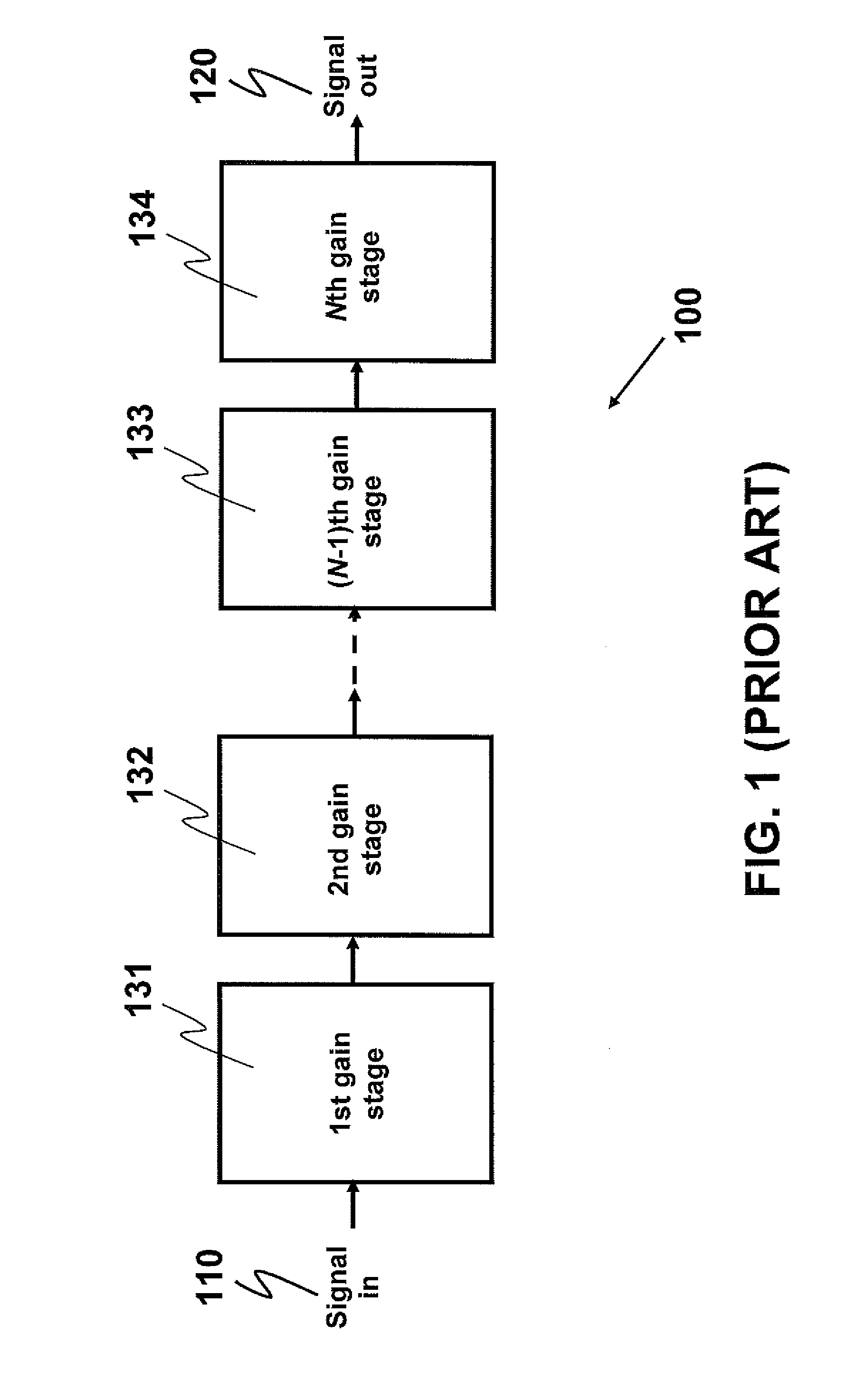
[0018]FIG. 1 illustrates an example of the multi-stage amplifier. A multi-stage amplifier 100 comprises N gain stages, including a first gain stage 131, a second gain stage 132, an (N−1)th gain stage 133 and an Nth gain stage 134. An input signal 110 is amplified in the first gain stage 131. The amplified signal at an output of the first gain stage 131 is fed to the second gain stage 132. This process repeats for subsequent gain stages up to the Nth gain stage 134, an output of which yields an output signal 120 of the multi-stage amplifier 100.

[0019]As used herein, a trailing stage is the last gain stage in the plurality of gain stages, and a non-trailing stage is one of the gain stages other than the ...


PUM


Abstract

This invention provides a multi-stage amplifier incorporating DC offset cancellation. The amplifier has a plurality of series-connected gain stages each of which comprises a differential amplifier unit generating a pair of differential outputs from a pair of differential inputs. In particular, a trailing stage in the plurality of gain stages comprises a digital DC offset cancellation module configured to compensate for a DC offset of the trailing stage's differential amplifier unit. The digital DC offset cancellation module comprises a comparator coupled to the pair of differential outputs of the trailing stage's differential amplifier unit for receiving such differential outputs as inputs for the comparator. Preferably, the comparator has an inherent DC offset that is substantially small. It is preferable that a non-trailing stage of the amplifier comprises an analog DC offset cancellation module for compensating for a DC offset of the non-trailing stage.

Description

COPYRIGHT NOTICE[0001]A portion of the disclosure of this patent document contains material, which is subject to copyright protection. The copyright owner has no objection to the facsimile reproduction by anyone of the patent document or the patent disclosure, as it appears in the Patent and Trademark Office patent file or records, but otherwise reserves all copyright rights whatsoever.FIELD OF THE INVENTION[0002]The present invention relates generally to DC offset cancellation for a multi-stage amplifier. In particular, this invention relates to hybrid DC offset cancellation involving a combination of digital DC offset cancellation and analog DC offset cancellation.BACKGROUND[0003]A direct-conversion receiver has gained popularity for use in multi-band, multi-standard communication systems. Despite this, the presence of DC offset is typically a problem for this receiver. In this receiver, a programmable gain amplifier is usually used. As the programmable gain amplifier usually prov...

Claims


Application Information

Patent Timeline
Patent Type & Authority Applications(United States)
IPC IPC(8): H03F3/45
CPCH03F3/45475H03F3/45973H03F3/45991H03F2200/405H03F2203/45048H03F2203/45522
Inventor GUO, HUIMINCHUNG, KAI CHEUNGQIAN, GANG
Owner HONG KONG APPLIED SCI & TECH RES INST
Why Eureka
Try Eureka