Elastic wave device

Active Publication Date: 2014-06-26
MURATA MFG CO LTD
View PDF5 Cites 2 Cited by
  • Summary
  • Abstract
  • Description
  • Claims
  • Application Information

AI Technical Summary

Benefits of technology

The present invention provides an elastic wave device with multiple elastic wave filters connected in parallel between an input and an output, which can reduce device size, insertion loss, and improve power handling. In one aspect, a reception filter chip and a transmission filter chip formed by an elastic wave filter chip are combined to form an elastic wave branching filter, reducing the size of the reception filter chip. Another aspect is the use of a ground electrode that overlaps with a common connection wiring line on the die-attach surface of the wiring board to improve isolation. The common connection wiring line is not in the elastic wave filter chip but in the wiring board, allowing for a reduction in the elastic wave filter chip size. These technical effects make the elastic wave device compact, low-loss, and efficient in managing power.

Problems solved by technology

Accordingly, the reception filter 1006 thus is undesirably increased in chip size.

Method used


Image

  • Elastic wave device
  • Elastic wave device
  • Elastic wave device

Examples


Embodiment Construction

[0031]With reference to the drawings, specific preferred embodiments of the present invention will be described below to reveal the present invention.

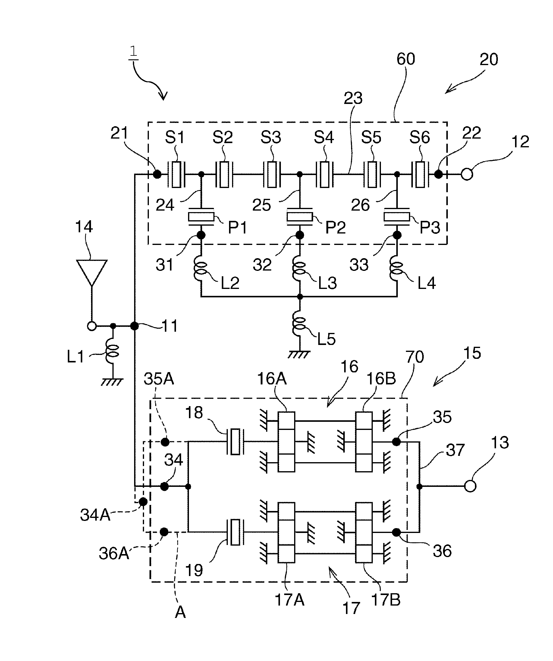
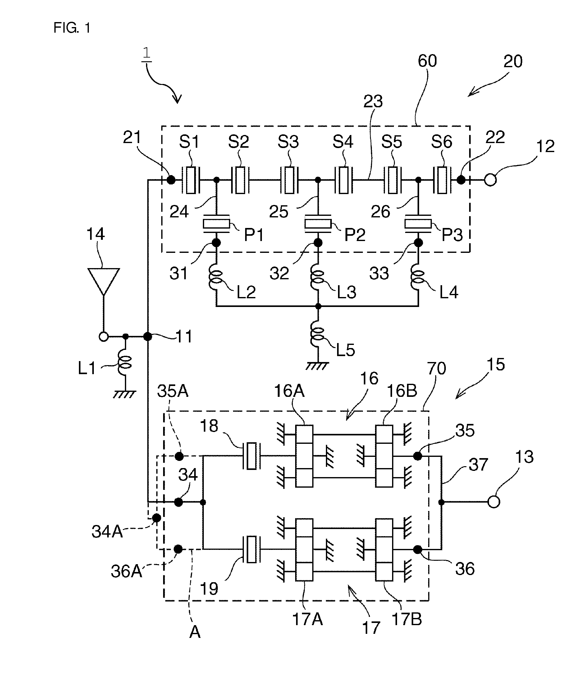
[0032]FIG. 1 is a schematic circuit diagram of an elastic wave device according to a first preferred embodiment of the present invention. An elastic wave device 1 according to the present preferred embodiment is a surface acoustic wave branching filter preferably used in UMTS Band 8 of cellular phones, for example. In UMTS Band 8, the transmission frequency band ranges from 880 MHz to 915 MHz, and the reception frequency band ranges from 925 MHz to 960 MHz.

[0033]The elastic wave device 1 includes an antenna terminal 11, a transmission terminal 12, and a reception terminal 13. A reception filter unit 15 is connected between the antenna terminal 11 and the reception terminal 13. The reception filter unit 15 preferably includes a reception filter chip 70 indicated by a broken line.

[0034]Meanwhile, a transmission filter unit 20 is connecte...


PUM


Abstract

An elastic wave device includes elastic wave filters connected in parallel between an input and an output, and has reduced size and insertion loss, and improved electric power handling capability. An elastic wave filter chip is mounted on a die-attach surface of a wiring board and includes an input signal terminal and output signal terminals. At least one of the input and output signal terminals includes a plurality of signal terminals. A common connection wiring line to commonly connect the plurality of signal terminals of the elastic wave filter chip is provided in the wiring board.

Description

BACKGROUND OF THE INVENTION[0001]1. Field of the Invention[0002]The present invention relates to an elastic wave device using elastic waves such as surface acoustic waves or boundary acoustic waves, and more specifically to an elastic wave device having a structure in which an elastic wave filter chip is mounted on a die-attach surface of a wiring board.[0003]2. Description of the Related Art[0004]In recent years, a branching filter has been connected to an antenna of a cellular phone or the like to isolate signals transmitted and received by the antenna. As the branching filter, an elastic wave branching filter using elastic waves such as surface acoustic waves, boundary acoustic waves, or bulk acoustic waves has been widely used.[0005]For example, Japanese Unexamined Patent Application Publication No. 2003-249842 discloses an example of this type of branching filter using elastic waves.[0006]As illustrated in FIG. 13, a branching filter 1001 described in Japanese Unexamined Patent...

Claims


Application Information

Patent Timeline
IPC IPC(8): H03H9/70H03H7/46
CPCH03H9/725H03H9/059H03H7/42H03H7/461
Inventor YASUDA, JUNPEI
Owner MURATA MFG CO LTD
Why Eureka
Try Eureka