Electronic equipment and flexible printed circuit

Active Publication Date: 2014-06-26
TRIVALE TECH LLC
View PDF4 Cites 42 Cited by
  • Summary
  • Abstract
  • Description
  • Claims
  • Application Information

AI Technical Summary

Benefits of technology

[0008]An object of the present invention is to provide electronic equipment having flexible printed circuits and the flexible printed circuits, which can avoid an adverse effect occurring inside and outside an electric appliance with ESD or EMI.
[0013]According to the electronic equipment of the present invention, the housing portion is preliminarily adapted to be grounded. This arrangement can exert an electric discharge operation in which a charge induced by ESD in an inner surface of the housing portion can be reliably dissipated outside the housing portion via the shield layer and the first grounding wiring portion. Accordingly, an element and the like configuring the drive circuit of the first substrate or the control circuit of the second substrate can be reliably prevented from destruction by ESD.
[0014]In addition, the electric discharge operation can significantly reduce an electromagnetic effect affecting the flexible printed circuits from an outside of the housing portion, and an electromagnetic effect affecting the outside of the housing portion from the flexible printed circuits, thereby also preventing an adverse effect by EMI.
[0015]Further, the shield layer which maintains an insulating relationship with the drive circuit can suppress an adverse effect affecting the drive circuit of the first substrate at a time when the electric discharge operation is exerted.

Problems solved by technology

At this state, there has been a case in which an abnormal voltage is applied to, or an abnormal current flows through a TFT panel and various sensors electrically connected to the FPC, or an IC and the like on a control board, causing a destruction thereof.
Further, there have been problems in which signal wiring on the FPC has an electromagnetic effect from an outside of the housing, and EMI (Electro-Magnetic Interference) emitted from wiring of the FPC is emitted to an outside world as it is to give an adverse effect to external equipment and the like.

Method used


Image

  • Electronic equipment and flexible printed circuit
  • Electronic equipment and flexible printed circuit
  • Electronic equipment and flexible printed circuit

Examples


first preferred embodiment

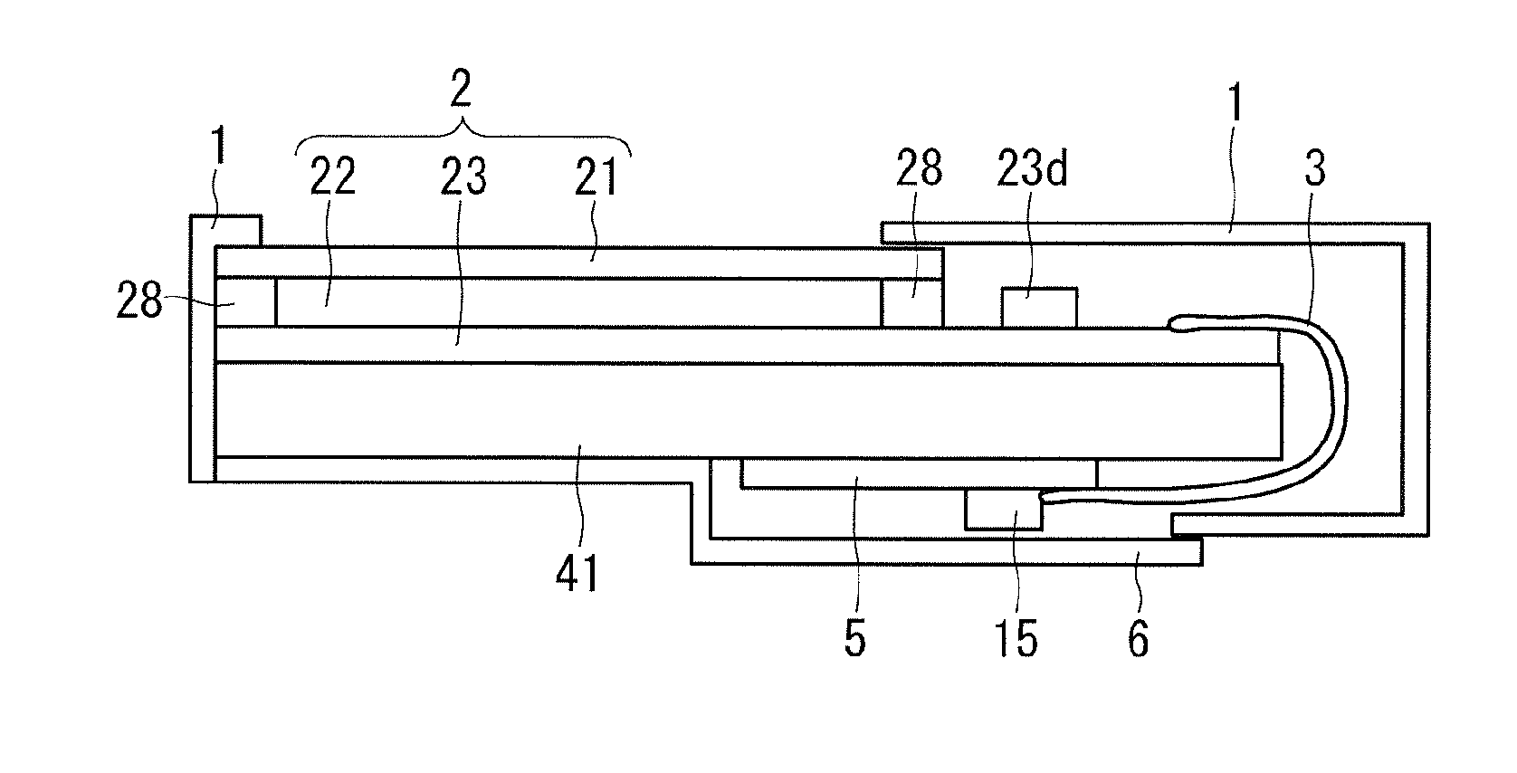
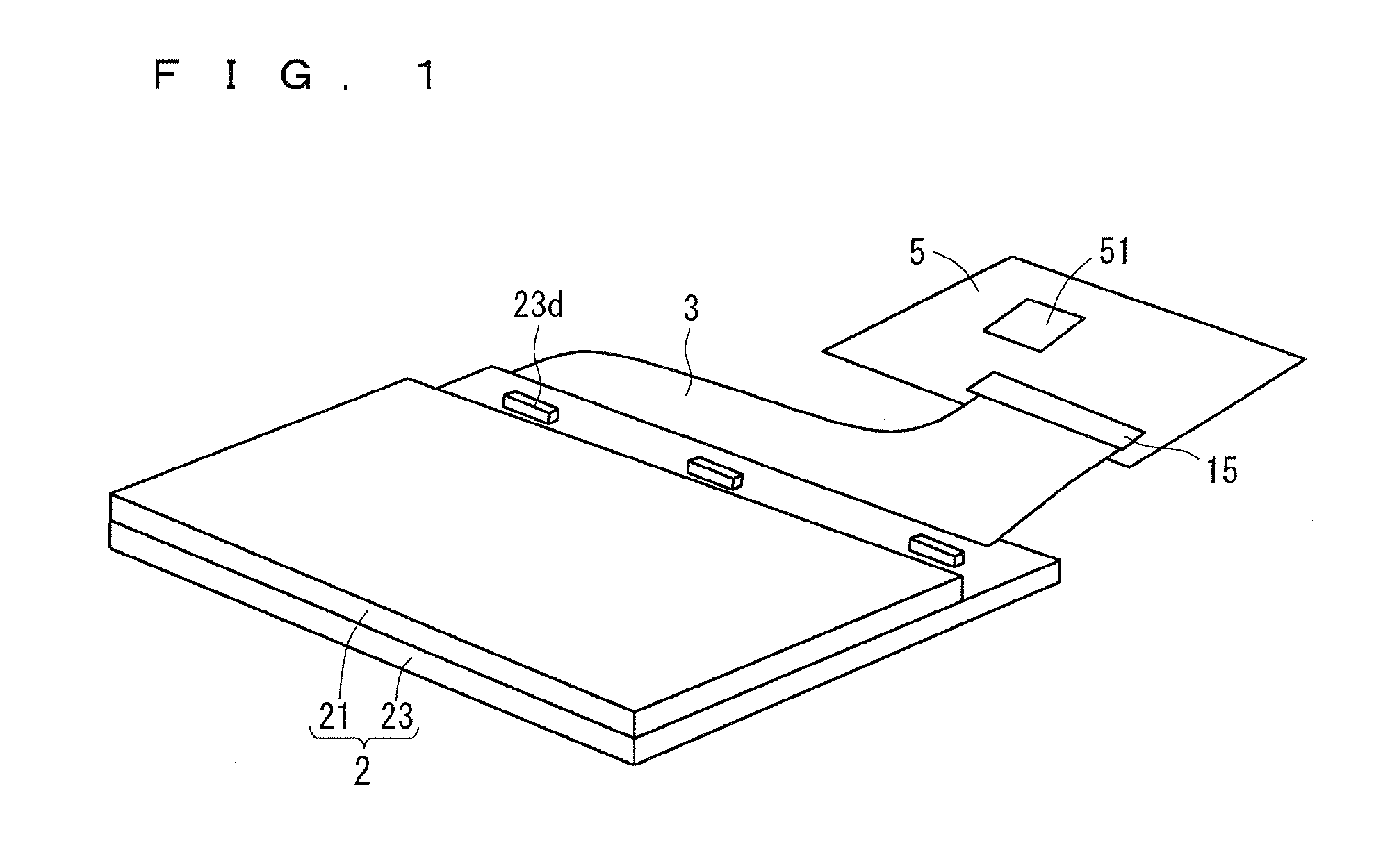
[0058]FIG. 9 is a cross-sectional view showing a structure of an FPC 30A used in a liquid crystal display device according to a first preferred embodiment of the present invention. As shown in the figure, a shield layer 34 is selectively formed on a front surface of a base film 32 having an insulating property to form a wiring layer 31 on a rear surface of the base film 32. Then, the wiring layer 31 is selectively provided with a connector connection terminal 35 (a second connecting portion) and a mounting terminal 36 (a first connecting portion) thereon, and is provided with a cover lay film 33 having an insulating property on a portion of the wiring layer 31 in which the terminals 35 and 36 are not formed. Nothing is formed on the shield layer 34, and thereby a front surface of the shield layer 34 is opened in an exposed state.

[0059]The FPC 30A having this type of structure is used such that the shield layer 34 formed at a front surface (a first major surface) side is brought into...

second preferred embodiment

[0110]The second preferred embodiment is for a liquid crystal display device using a refined FPC in which the mesh-like wiring pattern of the shield layer 34 of the FPC 30 (30A and 30B) becomes implementable to be refined.

[0111]The mesh-like wiring pattern is obtained simply by crossing over the first shield wiring L34a and the second shield wiring L34b each other, the first shield wiring L34a and the second shield wiring L34b being provided in opposite directions mutually with a 45-degree slant. However, there may cause following problems if simply obtaining the mesh-like wiring pattern as described above.

[0112]FIGS. 14A, 14B and 14C are plan views each schematically showing an overlapping relationship between the mesh-like wiring patterns and the plurality of wirings L31. As shown in FIG. 14A, when the mesh-like wiring pattern by the plurality of wirings L31, the first shield wiring L34a, and the second shield wiring L34b is viewed as transparent, there exist the wiring L31 crossi...


PUM

PropertyMeasurementUnit
applied voltageaaaaaaaaaa
flexibleaaaaaaaaaa
non-conductivityaaaaaaaaaa

Abstract

A shield layer is selectively formed on a front surface of a base film having an insulating property to form a wiring layer on a rear surface of the base film, and a connector connection terminal and a mounting terminal are selectively provided on the wiring layer. A liquid crystal display device is configured so as to be housed in a set housing, in a state that a TFT array substrate and a control board are connected to each other via an FPC having the structure as described above. In this case, the shield layer is provided in such a manner of opposing to an inner surface of the housing, the shield layer maintains an insulating relationship with the drive circuit, and is electrically connected to a portion of the housing via the first ground wiring portion.

Description

BACKGROUND OF THE INVENTION[0001]1. Field of the Invention[0002]The present invention relates to electronic equipment, such as a liquid crystal display device and the like, configured by having a flexible printed circuit in a housing, and to the flexible printed circuit.[0003]2. Description of the Background Art[0004]There is a case in which electronic equipment, such as a liquid crystal display device, a notebook type portable computer, and the like, has flexible printed circuits (FPC; Flexible Printed Circuits) therein in order to become implementable to reduce in size. As this type of electronic equipment, for example, a disclosure is made of a base unit on which a keyboard of a portable computer in Japanese Patent Application Laid-Open No. H7-154038 (1995) is mounted.[0005]The base unit has a box-like housing which houses a rigid circuit board on which various kinds of circuit components are mounted, and a plurality of functional components, such as a flexible disk drive and a h...

Claims


Application Information

Patent Timeline
Patent Type & Authority Applications(United States)
IPC IPC(8): H05K9/00G02F1/133H05K1/02
CPCH05K9/0054H05K1/028G02F1/13306H05K1/0224H05K1/0259H05K3/361H05K2201/0715H05K2201/09681G02F1/13452G02F1/133334
Inventor HASHIDO, RYUICHI
Owner TRIVALE TECH LLC
Why Eureka
Try Eureka