Zoom Lens

Inactive Publication Date: 2014-06-26
TAMRON
View PDF1 Cites 5 Cited by
  • Summary
  • Abstract
  • Description
  • Claims
  • Application Information

AI Technical Summary

Benefits of technology

[0053]The present invention employing the above lens arrangement can provide a high-power zoom lens ac

Problems solved by technology

Thus, the optical design of the optical systems in the zoom lenses have been complicated more and more

Method used


Image

  • Zoom Lens
  • Zoom Lens
  • Zoom Lens

Examples


example 1

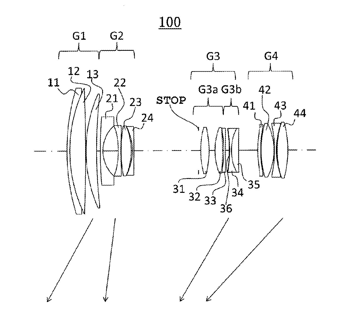
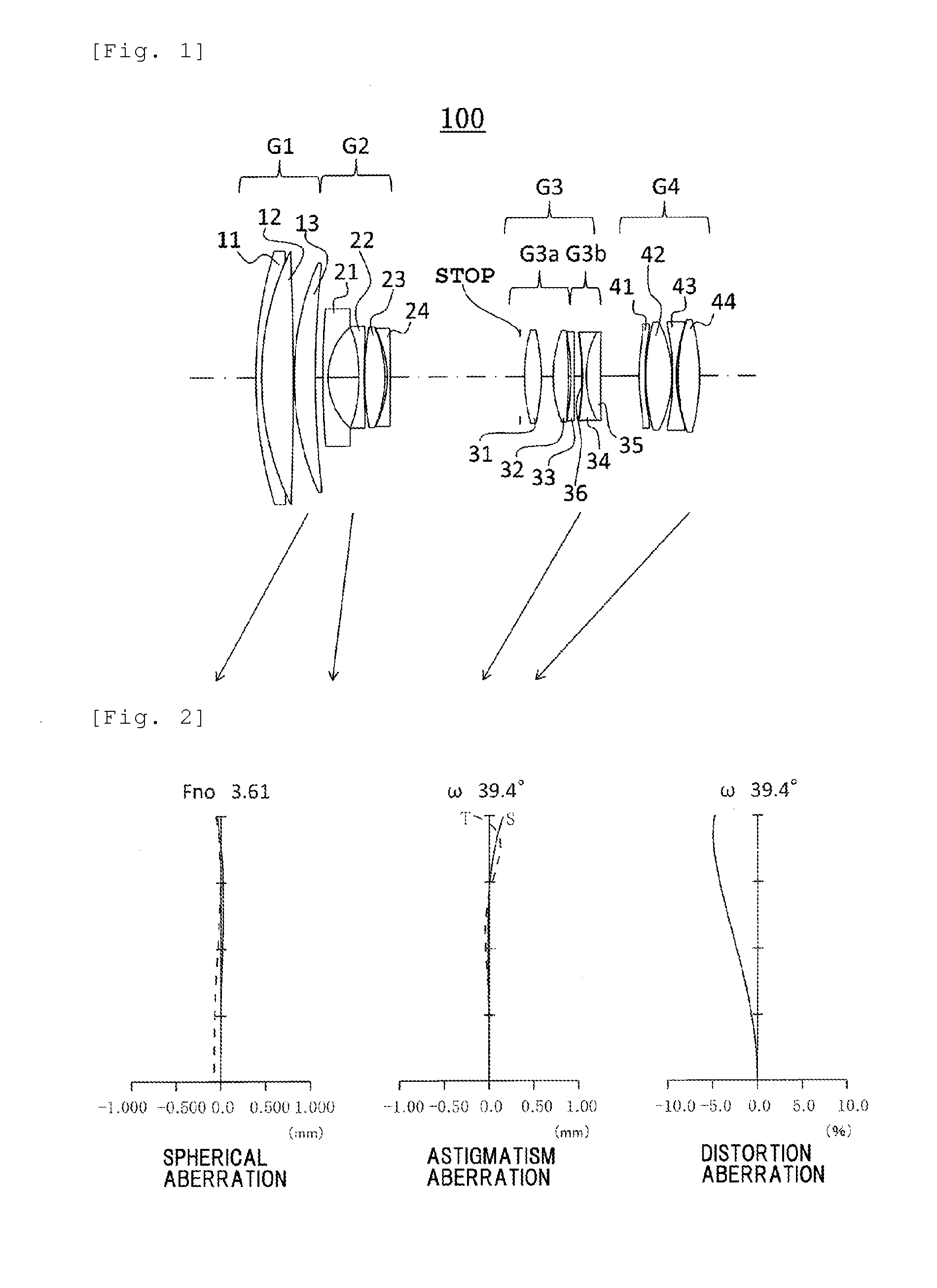
[0166]First, the zoom lens in Example 1 will be described. The zoom lens in Example 1 has the same lens arrangement as that of the optical system 100 (see FIG. 1). That is, the zoom lens in Example 1 consists of the first lens group G1 having a positive refractive power, the second lens group G2 having a negative refractive power, the third lens group G3 having a positive refractive power and the fourth lens group G4 having a positive refractive power arranged in this order from the object side as the lens groups constituting the optical system 100. As described above, the second lens group G2 is a focusing lens group that moves in focusing. Focusing of object from an infinite distance to a closest distance is performed by moving the second lens group G2 to the object side in focusing. In FIG. 1, the symbol STOP denotes an iris. In zooming from the wide-angle end to the telescope end, the respective lens groups travel forward and backward along the optical axis to change distance be...

example 2

[0178]Next, Example 2 will be described. Since the optical system 100 of the zoom lens in Example 2 is almost the same in lens arrangement as that in Example 1, only differences including the lens arrangement from those in Example 1 will be described. In the optical system 100 in Example 2, the group 3b among the groups 3a and 3b constituting the third lens group G3 shifts in the direction perpendicular to the optical axis for the vibration compensation. The shift of the group 3b for the vibration compensation is 0.093 mm, 0.191 mm, and 0.503 mm at the wide-angle end, the intermediate focal length and the telescope end respectively at a correction angle of 0.3°. In the present example, the groups 3a and 3b may also independently move along the optical axis direction for magnification change. The travel directions are preferable to be the same directions as those in Example 1. The same applies to Example 3 and following Examples.

[0179]Tables 4, 5, and 6 respectively show the data on ...

example 3

[0180]Next, Example 3 will be described. Since the optical system 100 of the zoom lens in Example 3 is almost the same in lens arrangement as that in Example 1 also, only differences including the lens arrangement from those in Example 1 will be described. In the optical system 100 in Example 3, the group 3b among the groups 3a and 3b constituting the third lens group G3 may also shift in the direction perpendicular to the optical axis for the vibration compensation. The shift of the group 3b for the vibration compensation is 0.092 mm, 0.190 mm, and 0.502 mm at the wide-angle end, the intermediate focal length and the telescope end respectively at a correction angle of 0.3°.

[0181]Tables 7, 8, and 9 respectively show the data on the respective lenses constituting the optical system 100 of the zoom lens in Example 3 including the data on the lens surfaces, the focal lengths and the aspherical surfaces. The numerical values of the respective expressions are also shown in FIG. 35. FIG. ...


PUM


Abstract

A high-power zoom lens that achieves size and price reduction, and at the same time provides high-quality imaging. This lens includes at least four lens groups arranged along an optical axis, which are moveable along the axis in order to achieve changes in magnification. The first, third, and fourth lens groups have positive refractive powers, and the second group has a negative refractive power. The second lens group includes a negative meniscus lens arranged closest to the object, provided with a convex surface at the object side. A negative lens is arranged next to the negative meniscus lens, and a negative lens provided with a concave surface at the object side is arranged closest to the image. The fourth lens group includes at least two positive lenses and one negative lens.

Description

CROSS-REFERENCE TO RELATED APPLICATIONS[0001]This application claims priority to Japanese Patent Application No. 2012-282949, filed Dec. 26, 2012, the disclosure of which is hereby incorporated in its entirety by reference.BACKGROUND OF THE INVENTION[0002]1. Field of the Invention[0003]The present invention relates to a zoom lens, and more particularly, to a high-power zoom lens.[0004]2. Background Art[0005]Recently, high-power zoom lenses having a magnification exceeding 10 have been paid attention as an interchangeable lens for a single-lens reflex camera. Such a zoom lens is required to have high-quality imaging performance, and also required to be compact and low price. Depending on the favor for a digital single-lens reflex camera in recent years, a demand on these performances is increasingly growing in the zoom lenses for amateur use.[0006]Since the high-power zoom lenses consist of a plurality of lens groups and should have moving mechanisms for moving the lens groups, the h...

Claims


Application Information

Patent Timeline
IPC IPC(8): G02B15/14
CPCG02B15/14G02B27/646G02B15/144113
Inventor ADACHI, NOBUYUKI
Owner TAMRON
Why Eureka
Try Eureka