Electromagnetic Interference Shielding and Strain Relief Structures For Coupled Printed Circuits

a technology of electromagnetic interference shielding and strain relief structure, which is applied in the direction of coupling device connection, electrical apparatus construction details, cross-talk/noise/interference reduction, etc., can solve the problems of electrical connection structure susceptible to damage, electromagnetic interference may be emitted from signal lines on printed circuits and other substrates,

Inactive Publication Date: 2014-06-26
APPLE INC
View PDF4 Cites 17 Cited by
  • Summary
  • Abstract
  • Description
  • Claims
  • Application Information

AI Technical Summary

Benefits of technology

[0006]The signal paths of the printed circuits are coupled together using electrical connection structures such as printed circuit board-to-board connectors, contacts joined by anisotropic conductive film, or contacts joined using solder. Strain relief and electromagnetic interference shielding structures may be provided that electromagnetically shield the electrical connection structures and help prevent the electrical connection structures from being damaged during movement of the printed circuits.

Problems solved by technology

If care is not taken, electromagnetic interference may be emitted from the signal lines on printed circuits and other substrates, particularly in the vicinity of electrical connection structures formed from printed circuit connectors or connections formed from anisotropic conductive film and or solder.
If not properly secured, electrical connection structures may also be susceptible to damage.

Method used


Image

  • Electromagnetic Interference Shielding and Strain Relief Structures For Coupled Printed Circuits
  • Electromagnetic Interference Shielding and Strain Relief Structures For Coupled Printed Circuits
  • Electromagnetic Interference Shielding and Strain Relief Structures For Coupled Printed Circuits

Examples


Embodiment Construction

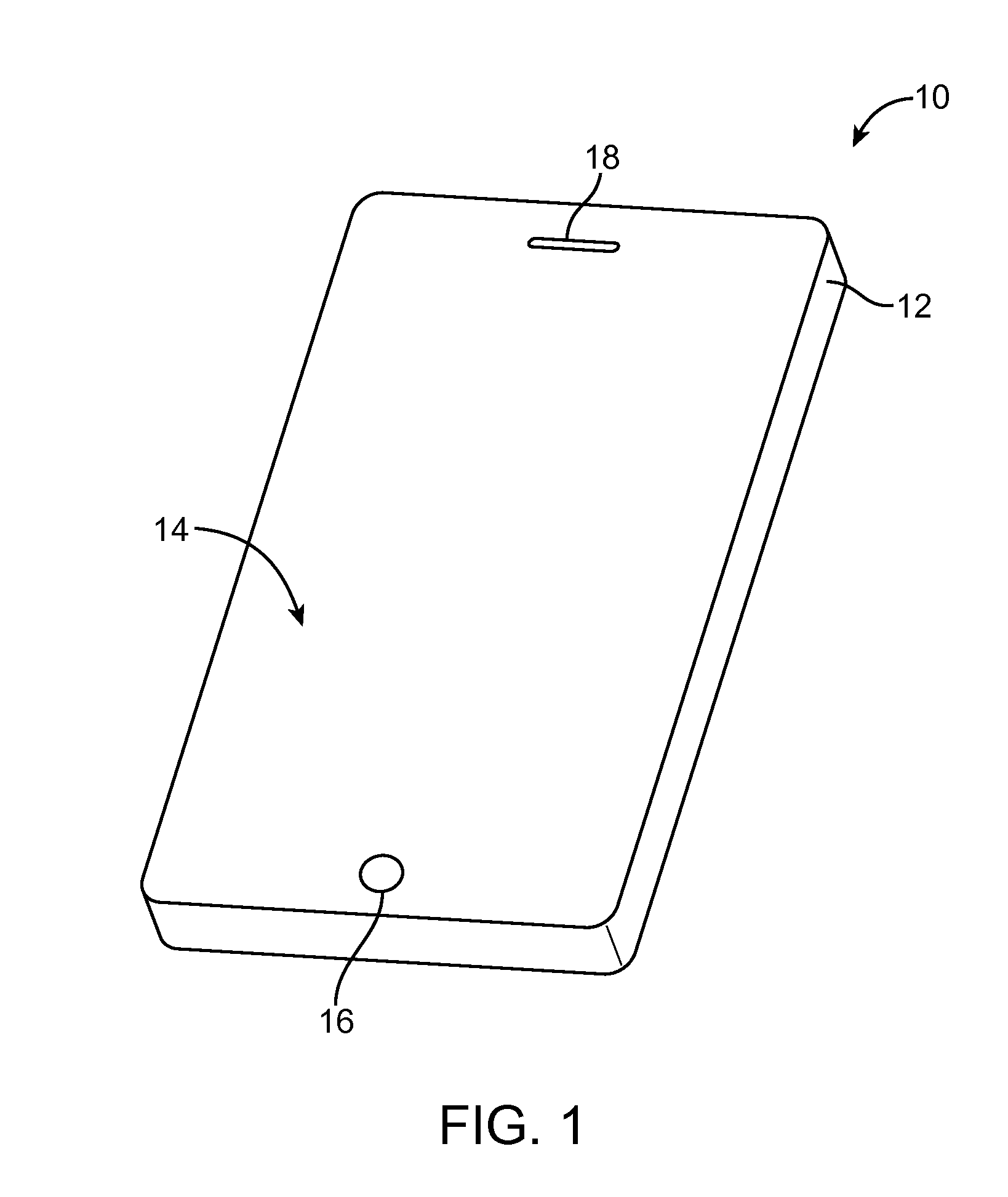
[0045]An illustrative electronic device that may be provided with strain relief structures and electromagnetic interference shielding structures for electromagnetically shielding electrical connection structures between printed circuits is shown in FIG. 1. Electronic devices such as device 10 of FIG. 1 may be cellular telephones, media players, other handheld portable devices, somewhat smaller portable devices such as wrist-watch devices, pendant devices, or other wearable or miniature devices, gaming equipment, tablet computers, notebook computers, desktop computers, televisions, computer monitors, computers integrated into computer displays, or other electronic equipment.

[0046]In the example of FIG. 1, device 10 includes a display such as display 14. Display 14 has been mounted in a housing such as housing 12. Housing 12, which may sometimes be referred to as an enclosure or case, may be formed of plastic, glass, ceramics, fiber composites, metal (e.g., stainless steel, aluminum, ...


PUM

PropertyMeasurementUnit
conductiveaaaaaaaaaa
anisotropic conductiveaaaaaaaaaa
resilientaaaaaaaaaa

Abstract

Electrical components in an electronic device are mounted on substrates such as printed circuits. Printed circuits contain signal paths formed from metal traces. The signal lines in the signal paths of the printed circuits are coupled together using electrical connection structures such as printed circuit board-to-board connectors, contacts joined by anisotropic conductive film, or contacts joined using solder. Electrical connection structures may be surrounded by conductive resilient ring-shaped structures such as conductive foam structures or spring structures. The conductive foam structures may be provided with a metal layer with which the conductive foam structures are soldered to a ring of metal on a printed circuit. Strain relief structures may be formed from an elastomeric ring that surrounds the electrical connection structures or an overmolded plastic structure. Coating layers and conductive plastic may be used in providing strain relief structures with electromagnetic interference shielding capabilities.

Description

BACKGROUND[0001]This relates generally to electronic devices and, more particularly, to electronic devices with electromagnetic interference shielding and strain relief structures.[0002]Electronic devices include electrical components. Components are mounted on substrates such flexible printed circuits and rigid printed circuit boards. Interconnect lines formed from patterned metal traces carry signals within the substrates. For example, metal traces may carry signals between integrated circuits on a printed circuit.[0003]Substrates such as printed circuits are often coupled together using connectors such as board-to-board connectors and using connections formed from conductive material such as anisotropic conductive film or solder. If care is not taken, electromagnetic interference may be emitted from the signal lines on printed circuits and other substrates, particularly in the vicinity of electrical connection structures formed from printed circuit connectors or connections forme...

Claims


Application Information

Patent Timeline
Patent Type & Authority Applications(United States)
IPC IPC(8): H05K1/02H05K1/11H05K13/00H05K9/00
CPCH05K1/028H05K9/0009H05K13/00H05K1/11H01R12/79H01R13/6595H05K1/0219H05K3/363H05K3/368H05K7/142H05K9/0022H05K2201/0311H05K2201/0314H05K2201/09063H05K2201/10189H05K2201/10409Y10T29/49126
Inventor MALEK, SHAYANWITTENBERG, MICHAEL B.COHEN, SAWYER I.SHUKLA, ASHUTOSH Y.
Owner APPLE INC
Why Eureka
Try Eureka