
Systems and methods for source switching and voltage generation

Active Publication Date: 2014-06-26
ON BRIGHT ELECTRONICS SHANGHAI
View PDF8 Cites 45 Cited by
  • Summary
  • Abstract
  • Description
  • Claims
  • Application Information

AI Technical Summary

Benefits of technology

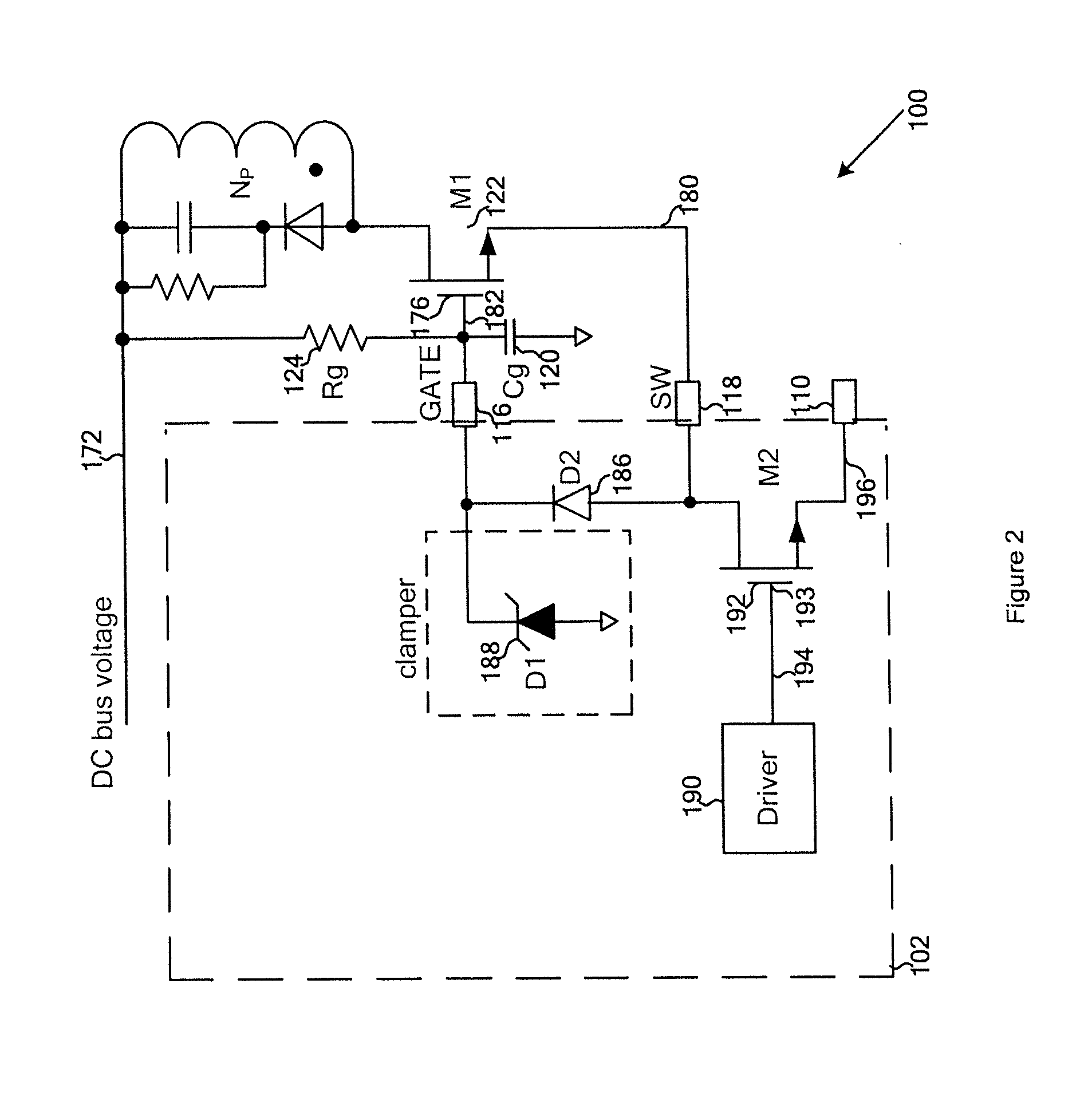
The present invention offers several benefits over conventional techniques. It provides a way to switch sources using an internal transistor in a system controller. It also reduces the minimum voltage needed to prevent a system from shutting down due to low power. Additionally, it allows a capacitor to be quickly charged during a start-up process, ensuring a steady supply of power.

Problems solved by technology

But high voltage start-up circuits for such switch-mode power supplies are usually manufactured using an expensive high voltage semiconductor process.
In addition, the conventional switch-mode power supplies often suffer from slow start-up and high standby power consumption.

Method used


Image

  • Systems and methods for source switching and voltage generation
  • Systems and methods for source switching and voltage generation
  • Systems and methods for source switching and voltage generation

Examples


Embodiment Construction

[0023]The present invention is directed to integrated circuits. More particularly, the invention provides systems and methods for source switching and / or internal voltage generation. Merely by way of example, the invention has been applied to a power conversion system. But it would be recognized that the invention has a much broader range of applicability.

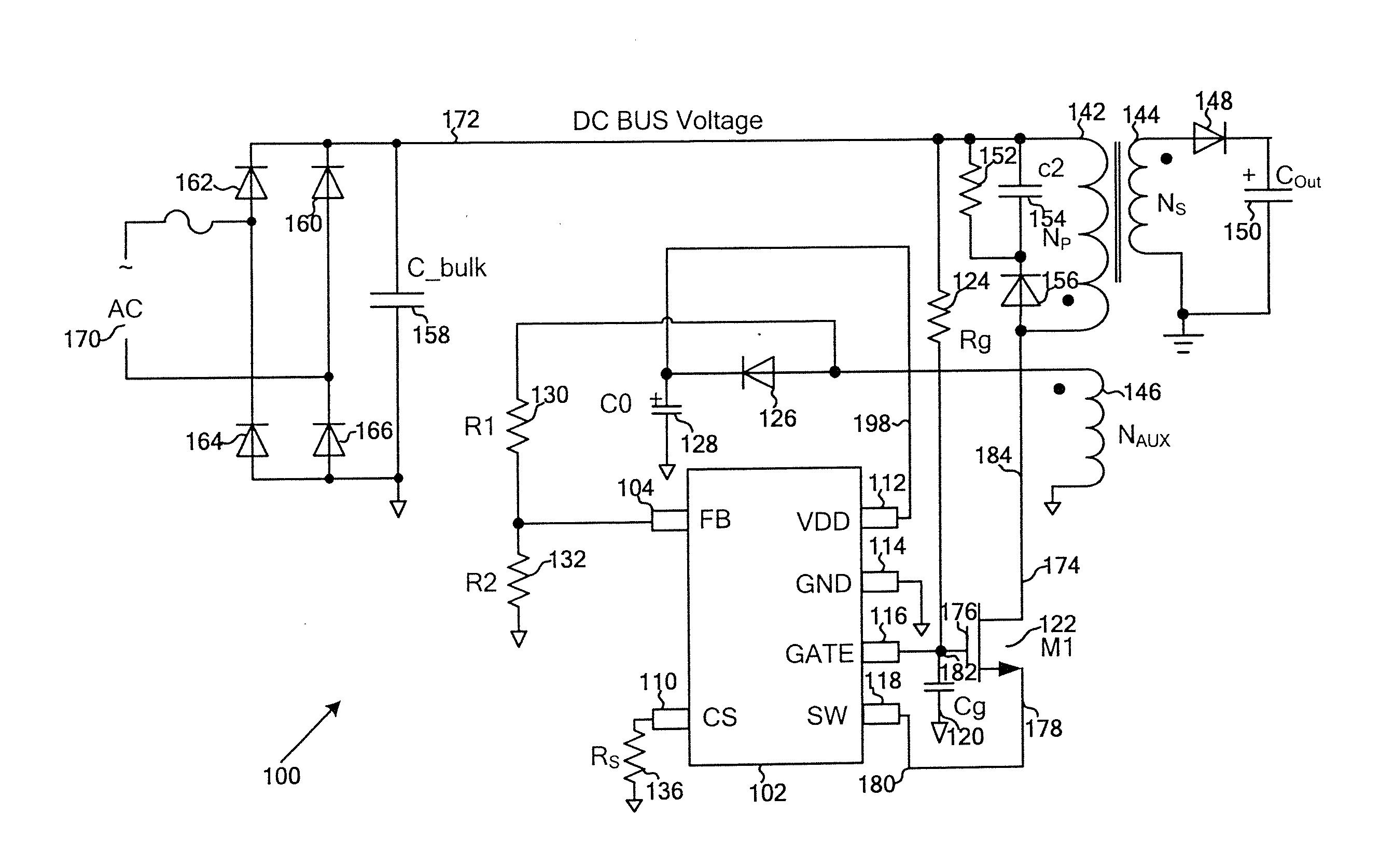
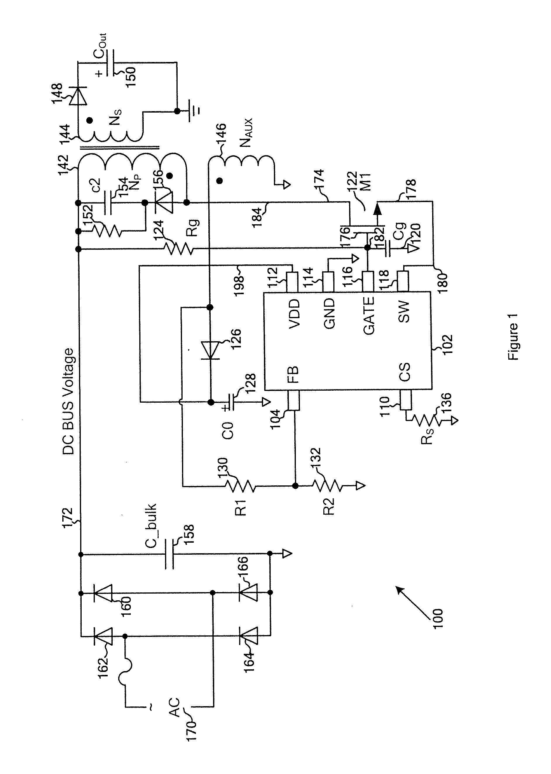
[0024]FIG. 1 is a simplified diagram showing a power conversion system with source switching and / or internal voltage generation according to an embodiment of the present invention. This diagram is merely an example, which should not unduly limit the scope of the claims. One of ordinary skill in the art would recognize many variations, alternatives, and modifications.

[0025]The power conversion system 100 includes a controller 102, a primary winding 142, a secondary winding 144, an auxiliary winding 146, a switch 122, capacitors 120, 128, 134, 150, 154 and 158, resistors 124, 130, 132, 136 and 152, a full wave rectifying bridge inclu...


PUM


Abstract

System and method for regulating a power conversion system. An example system controller for regulating a power conversion system includes a first controller terminal associated with a first controller voltage and coupled to a first transistor terminal of a first transistor, the first transistor further including a second transistor terminal and a third transistor terminal, the second transistor terminal being coupled to a primary winding of a power conversion system, a second controller terminal associated with a second controller voltage and coupled to the third transistor terminal, and a third controller terminal associated with a third controller voltage. The first controller voltage is equal to a sum of the third controller voltage and a first voltage difference. The second controller voltage is equal to a sum of the third controller voltage and a second voltage difference.

Description

1. CROSS-REFERENCES TO RELATED APPLICATIONS[0001]This application claims priority to Chinese Patent Application No. 201210564309.4, filed Dec. 21, 2012, incorporated by reference herein for all purposes.2. BACKGROUND OF THE INVENTION[0002]The present invention is directed to integrated circuits. More particularly, the invention provides systems and methods for source switching and / or internal voltage generation. Merely by way of example, the invention has been applied to a power conversion system. But it would be recognized that the invention has a much broader range of applicability.[0003]Conventional switch-mode power supplies often implement gate controlled switching using high voltage power MOSFETs. But high voltage start-up circuits for such switch-mode power supplies are usually manufactured using an expensive high voltage semiconductor process. In addition, the conventional switch-mode power supplies often suffer from slow start-up and high standby power consumption.[0004]Hen...

Claims


Application Information

Patent Timeline
IPC IPC(8): H02M3/335
CPCH02M3/33523H02M3/33507
Inventor YANG, JIQINGZHOU, JUNZHU, LIQIANGLUO, QIANGFANG, LIEYI
Owner ON BRIGHT ELECTRONICS SHANGHAI
Learn More