Apparatus and method of employing self-assembled molecules to function as an electron injection layer of OLED

Inactive Publication Date: 2005-02-10
WINTEK CORP
View PDF4 Cites 4 Cited by
  • Summary
  • Abstract
  • Description
  • Claims
  • Application Information

AI Technical Summary

Benefits of technology

[0006] Therefore the primary object of the invention is to resolve the aforesaid disadvantages. The invention employs the dipolar properties of self-assembled molecules and uses the self-assembled molecules as the electron injection layer (EIL) to achieve a fabrication process of a high stability and through material having recurrence to increase electron injection power of the electron injection layer, thereby to increase light emitting efficiency and reduce the threshold voltage.
[0007] The invention mainly uses OLEDs that employ self-assembled molecules as the electron injection layer (EIL). First, a cathode metal layer is formed on a substrate; next, a dipolar self-assembled molecule film is formed on the cathode metal layer by a dipping or vaporizing to serve as an electron injection layer (EIL); then an Electron Transport Layer (ETL), an Light Emitting Layer, and a Hole Transport Layer (HTL) are plated by vaporizing in this order; finally a conductive film is plated by sputtering to serve as the anode. Through the dipolar properties of the self-assembled molecules, and bonding of the doner and the cathode metal, the dipolar direction formed in the self-assembled molecules can help to increase electron injection efficiency thereby increase light emitting efficiency of OLED elements and reduce the threshold voltage of the OLED elements.

Problems solved by technology

But the metal of low function often is more active and easy to oxidize with moisture and result in damage of the cathode.
Hence it is more difficult to overcome the energy barrier required for injecting electrons.
However, the generally used LiF for electron injection layer has industrial problems.
As the film thickness of LiF must be controlled within 2 nm, the problems in fabrication stability and recurrence are more difficult to overcome.

Method used


Image

  • Apparatus and method of employing self-assembled molecules to function as an electron injection layer of OLED
  • Apparatus and method of employing self-assembled molecules to function as an electron injection layer of OLED
  • Apparatus and method of employing self-assembled molecules to function as an electron injection layer of OLED

Examples


Embodiment Construction

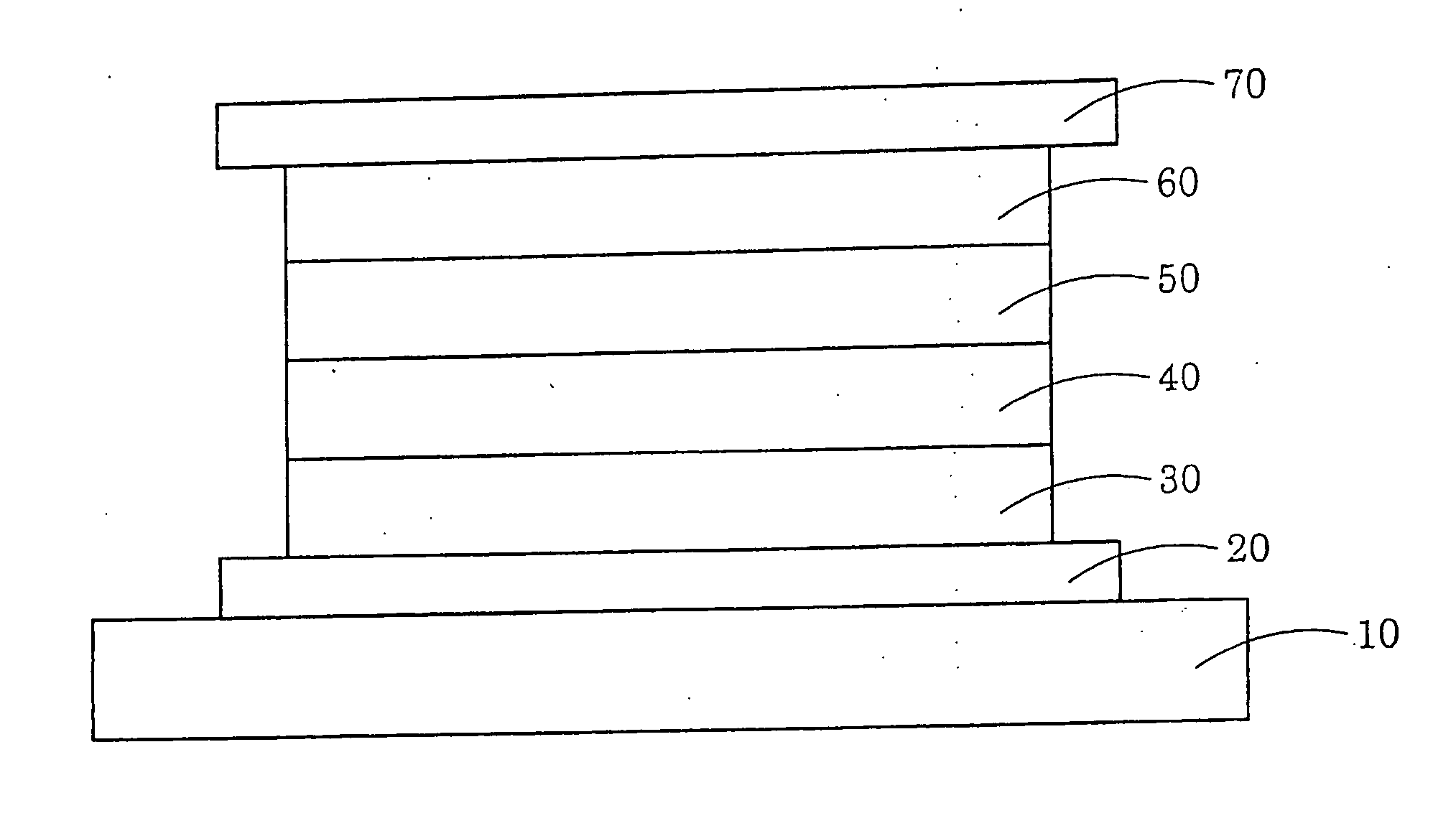
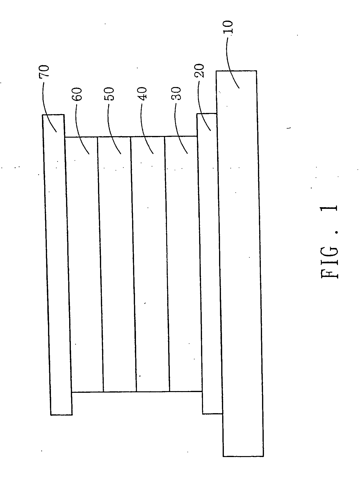
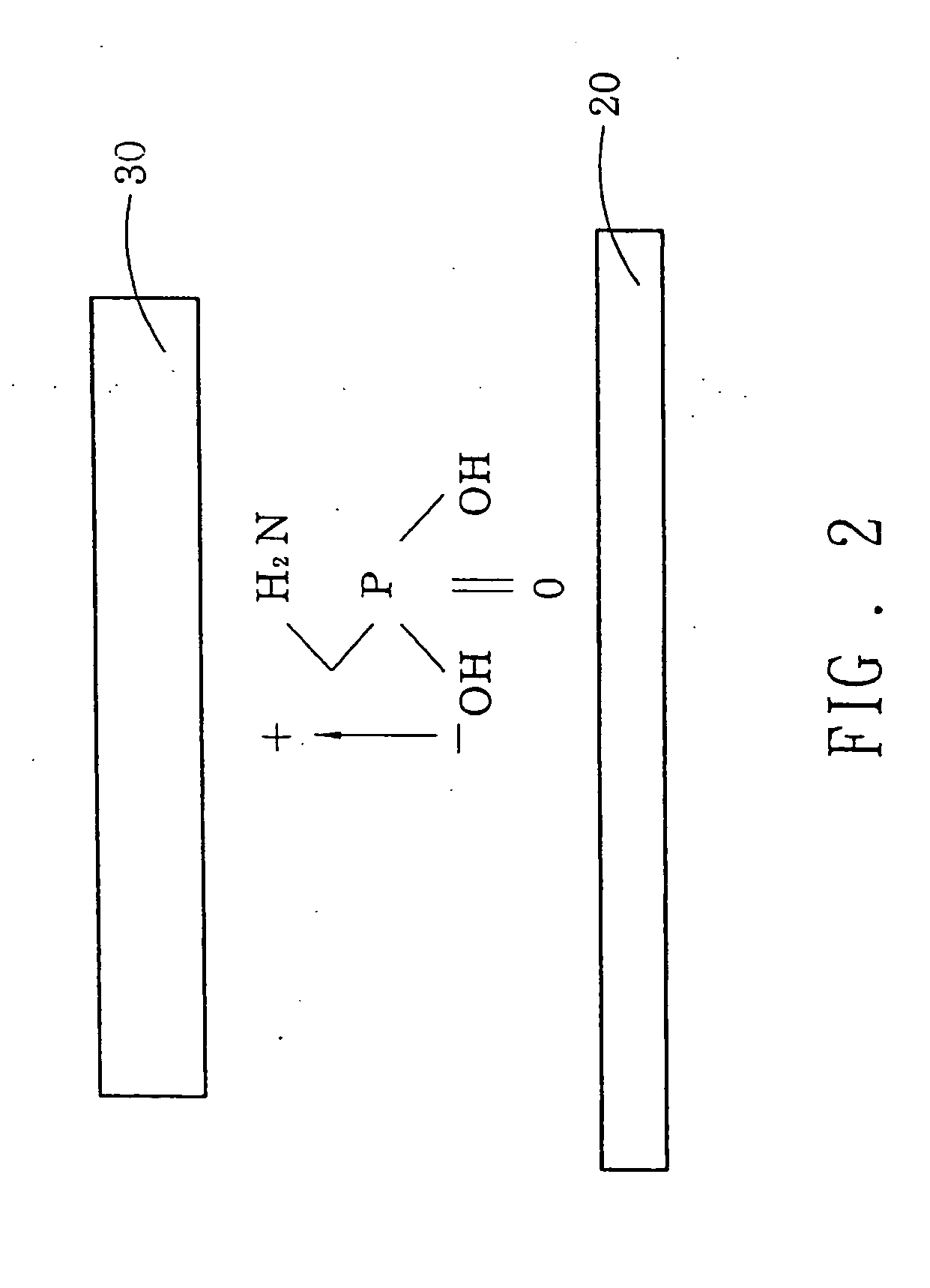
[0012] Refer to FIG. 1 for the structure of the invention. The invention includes an OLED substrate 10 upon which a cathode metal layer 20 is formed. The cathode metal layer 20 is made from a composite material consisting of metal of alkaline family or alkaline earth family and Al or Ag, or ITO or IZO. Next, a dipolar self-assembled molecule film 30 is formed on the surface of the cathode metal layer 20 by a dipping or vaporizing. The present self-assembled molecules are aminomethyl phosphonic acid (AMPA). The film thus formed serves as the electron injection layer of OLED elements. Then an Electron Transport Layer (ETL) 40, an Emitting Layer 50, and a Hole Transport Layer (HTL) 60 are plated on the electron injection layer in this order by vaporizing. Finally a conductive film is plated by sputtering to serve as the anode layer 70.

[0013] In the general molecules, the acidic root are easy to become acceptor. The alkaline root is doner. The acidic root is easy to form bonding with m...


PUM

PropertyMeasurementUnit
Electric potential / voltageaaaaaaaaaa
Efficiencyaaaaaaaaaa

Abstract

An apparatus and method of employing self-assembled molecules to function as an electron injection layer of organic light emitting diodes (OLEDs) uses self-assembled molecules to function as an electron injection layer. A dipolar self-assembled molecules film is formed on a cathode metal layer to serve the electron injection layer. The self-assembled molecules have dipolar properties. The doner and the cathode metal layer form a key bond. The resulting dipolar direction formed in the self-assembled molecules can increase electron injection efficiency, thereby increase light emitting efficiency of OLED elements and reduce the threshold voltage of the OLED elements.

Description

FIELD OF THE INVENTION [0001] The present invention relates to an apparatus and method that employs self-assembled molecules to function as an electron injection layer of organic light emitting diodes (OLEDs) and particularly to an approach that use dipolar properties of self-assembled molecules to enhance electron injection capability and transport efficiency. BACKGROUND OF THE INVENTION [0002] OLED has many advantages, such as self illumination, small thickness, fast response time, wide viewing angle, excellent resolution, great brightness, adaptable to flexible panels and wide range of use temperature. It is being considered the most promising technique for the new generation of flat display device after Thin Film Transistor Liquid Crystal Display (TFT-LCD). The principle of OLED uses material characteristics to couple electrons and holes on a emitting layer to generate energy to raise light emitting molecules from a base state to an agitated state. When the electrons are returne...

Claims


Application Information

Patent Timeline
IPC IPC(8): H01L51/30H01L51/50
CPCH01L51/5092H01L51/0075H10K85/701H10K50/171
Inventor CHU, TA-YALIN, GWO-SEN
Owner WINTEK CORP
Why Eureka
Try Eureka