Control device for hybrid vehicle

a control device and hybrid technology, applied in the direction of electric devices, machines/engines, process and machine control, etc., can solve the problems of limiting battery output or motor output, and the strategy will not be applicable, so as to reduce the required motor torque, suppress the heating and reduce the slip amount of the second engagement element

Inactive Publication Date: 2014-06-26
NISSAN MOTOR CO LTD
View PDF7 Cites 18 Cited by
  • Summary
  • Abstract
  • Description
  • Claims
  • Application Information

AI Technical Summary

Benefits of technology

[0012]That is, since the motor rotates at a rotation speed lower than the engine speed, it is possible to reduce the slip amount of the second engagement element so that it is possible to suppress the heating amount of the second engagement element. Further, since the engine is in operating state and the first engagement element is slip-engaged, a driving torque from the engine is transferred via the first engagement clutch so the required motor torque may be reduced by the engine torque amount transmitted.
[0013]As a result, it is possible to reduce the motor torque during a motor slip drive control mode to be executed when the load of the driving force transmission system is high.

Problems solved by technology

However, in the control device of the hybrid vehicle described above, although the slip rotation speed of the second engagement element CL2 is reduced using the motor, the strategy will not be applicable when a battery output or a motor output is restricted.

Method used


Image

  • Control device for hybrid vehicle
  • Control device for hybrid vehicle
  • Control device for hybrid vehicle

Examples


first embodiment

[0029]First, description will be given of the configuration.

[0030]The configuration of the control device in a hybrid vehicle in the first embodiment is described by dividing into a “system configuration”, a “control configuration of the integrated controller”, and a “driving mode transition control configuration”, respectively.

[System Configuration]

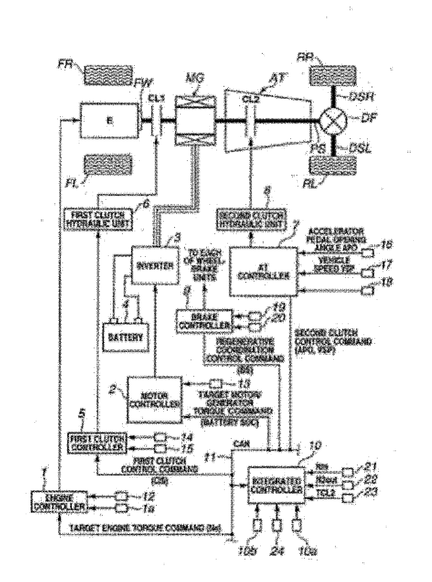
[0031]FIG. 1 is an overall system diagram showing a rear-wheel drive hybrid vehicle control device to which the first embodiment is applied. Below, with reference to FIG. 1, the system configuration (configurations of driving system and control system) is described.

[0032]As shown in FIG. 1, the driving system in a hybrid vehicle includes an engine E, a first clutch CL1 (a first engagement element), a motor generator MG (motor), a second clutch CL2 (second engagement element), an automatic transmission AT, a propeller shaft PS, a differential DF, a left drive shaft DSL, a right drive shaft DSR, a left rear wheel RL (drive wheel), and a ri...

second embodiment

[0161]In the second embodiment, in the MWSC+CL1 slip control, the target CL1 torque is given by the target driving torque.

[0162]To describe the structure, since the configuration of the second embodiment is the same as the first embodiment except for step 9 inFIG. 7, no specific figure is shown. Thus, a description is give of the step 7 in the second embodiment.

[0163]In step S9, following the YES determination at step S8, the system performs the MWSC+CL1 slip control process, and the process proceeds to RETURN. Specifically, in the MWSC+CL1 slip control process, the first clutch CL1 is slip-engaged by setting a target CL1 torque as the (target driving torque), the engine E is feedback controlled to reach an idle rotation speed, the motor generator MG is feedback controlled to attain a target rotation speed (yet, lower value than the idle speed) obtained by adding the output side rotation speed Nxl2out of the second clutch CL2 a predetermined rotation speed β′. Further, the second cl...

third embodiment

[0171]In the third embodiment, in the MWSC+CL1 slip control, the target CL1 torque is given by the (target driving torque+power generation torque).

[0172]To describe the structure, with the exception of step S9 in FIG. 7, the configuration of the third embodiment is the same as the first embodiment. Therefore, specific figures are omitted. Below, a description of the step S9 in the third embodiment is given.

[0173]In step S9, following the YES determination at step S8, the system performs the MWSC+CL1 slip control process, and the process proceeds to RETURN. In the MWSC+CL1 slip control process, specifically, the first clutch CL1 is slip-engaged by setting the target CL1 torque as the (target driving torque+power generation torque) maintaining the engine in operation, and the engine E is feedback controlled in order for the engine to rotate at idle speed. Further, the motor generator MG is feedback controlled so as to attain a target rotation speed (yet, at lower value than idle speed...


PUM


Abstract

A control device for a hybrid vehicle has an engine, a motor configured to output a driving force of the vehicle and performing a startup of the engine, a first engagement element interposed between the engine and the motor that selectively connects and releases the engine and the motor, a second engagement element interposed between the motor and a driving wheel that selectively engages and releases the motor and the driving wheel, a driving force transmission system load detecting device that either detects or estimates a load of the driving force transmission system, and an engine/motor slip drive control unit that slip engages the first engagement element with the engine maintaining in rotating state at a predetermined rotation speed, and slip engages the second engagement element with the motor at a rotation speed lower than the predetermined rotation speed.

Description

CROSS-REFERENCE TO RELATED APPLICATIONS[0001]This application claims priority based on Japanese Patent Application No. 2011-173770 filed in Japan Patent Office on Aug. 9, 2011, the disclosures of all of which are incorporated herein by reference in its entirety.BACKGROUND[0002]1. Technical Field[0003]The present invention relates to a control device for a hybrid vehicle which has an engine and an electric motor as a driving source with a first engagement element interposed between the engine and the motor engine while second engagement element interposed between the motor and a driving wheel.[0004]2. Related Art[0005]In such a hybrid vehicle having a first engagement element between the engine and the motor and having a second engagement element between the motor and the driving wheel, the second engagement element is protected by suppressing excessive heat generation when the load in a driving force transmission system is large. A system is known (see Patent Document 1, for example...

Claims


Application Information

Patent Timeline
Patent Type & Authority Applications(United States)
IPC IPC(8): B60W20/00B60W10/06B60W10/08B60W10/02B60L50/16
CPCB60K6/48B60K2006/4825B60L7/24B60L15/2009B60L15/2054B60L50/16B60L2210/40B60L2220/14B60L2240/12B60L2240/421B60L2240/423B60L2240/507B60L2240/642B60L2260/26B60W10/02B60W10/06B60W10/08B60W20/00B60W20/15B60W30/184B60W2510/1025B60W2710/025B60W2710/0644B60W2710/081F02D29/02Y02T10/64Y02T10/7072Y02T10/72Y02T90/16Y10S903/93B60L7/14B60L58/12B60L2240/36B60L2240/441B60L2240/443B60L2240/445B60L2240/486B60L2260/44B60W2510/0241B60W2552/15B60Y2300/429B60K6/46Y02T10/62Y02T10/70B60W20/10
Inventor TSUCHIKAWA, HARUHISAKOGURE, YUYASHIMOYAMA, HIROKI
Owner NISSAN MOTOR CO LTD
Why Eureka
Try Eureka