Aircraft engine systems and methods for operating same

a technology of aircraft engine and engine system, which is applied in the direction of engine/propulsion fuel heating, fuel system for specific fuels, machines/engines, etc., can solve the problems of low engine system efficiency and limited capacity of conventional liquid fuels for absorbing or transporting hea

Inactive Publication Date: 2014-07-03
GENERAL ELECTRIC CO
View PDF23 Cites 27 Cited by
  • Summary
  • Abstract
  • Description
  • Claims
  • Application Information

AI Technical Summary

Problems solved by technology

Use of compressor air for cooling may lower efficiency of the engine system, and conv

Method used


Image

  • Aircraft engine systems and methods for operating same
  • Aircraft engine systems and methods for operating same
  • Aircraft engine systems and methods for operating same

Examples


Embodiment Construction

[0029]Referring to the drawings herein, identical reference numerals denote the same elements throughout the various views.

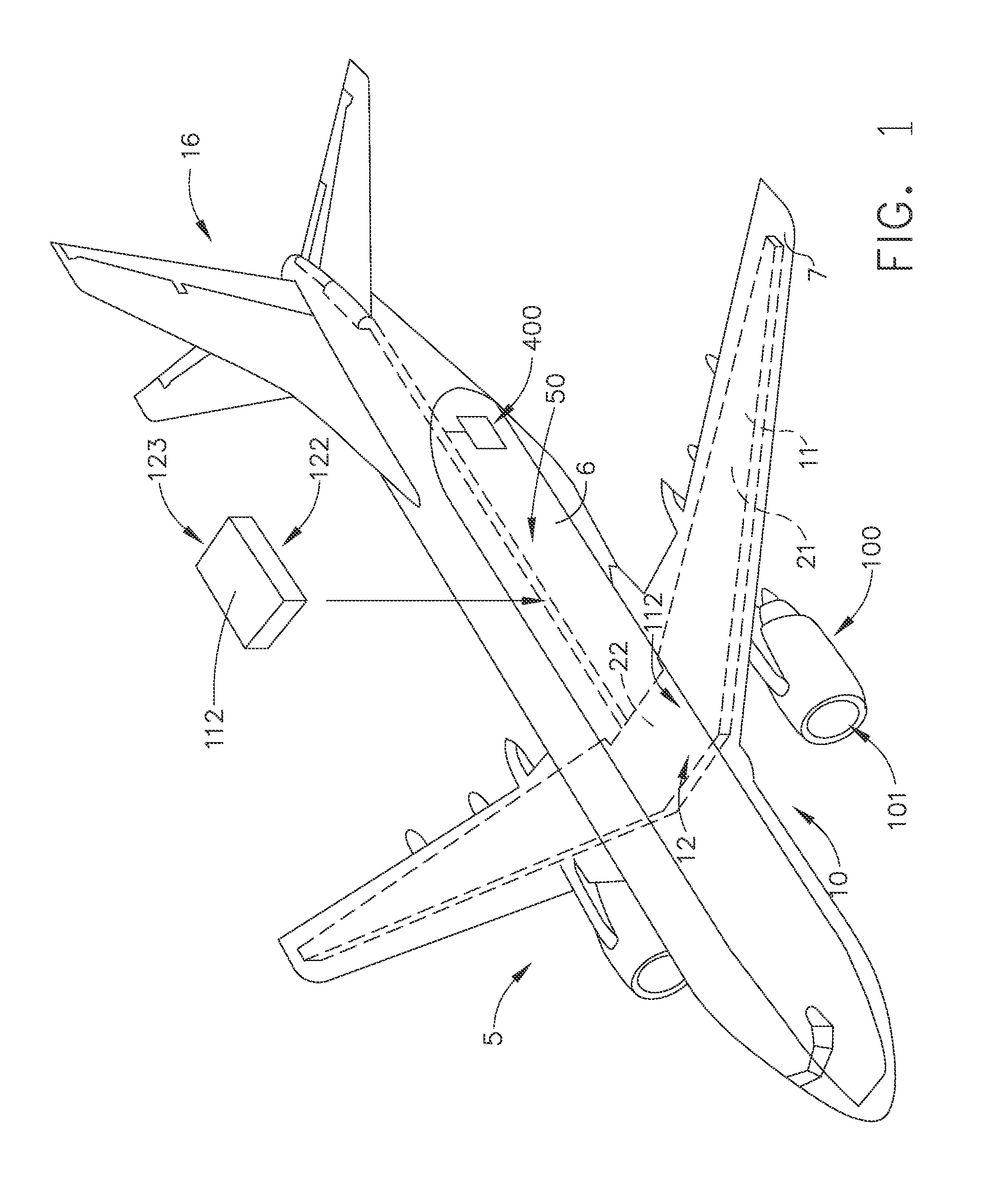
[0030]FIG. 1 shows an aircraft system 5 according to an embodiment of the present invention. The aircraft system 5 has a fuselage 6 and wings 7 attached to the fuselage. The aircraft system 5 has a propulsion system 100 that produces the propulsive thrust required to propel the aircraft system in flight. Although the propulsion system 100 is shown attached to the wing 7 in FIG. 1, in other embodiments of the present invention it may be coupled to other parts of the aircraft system 5, such as, the tail portion 16.

[0031]The aircraft system 5 has a fuel storage system 10 for storing one or more types of fuels that are used in the propulsion system 100. The aircraft system 5 shown in FIG. 1 uses two types of fuels, as explained further below herein. Accordingly, the aircraft system 5 comprises a first fuel tank 21 capable of storing a first fuel 11 and a second fuel...


PUM


Abstract

A gas turbine propulsion system includes a system which utilizes a cryogenic liquid fuel for a non-combustion function.

Description

CROSS-REFERENCE TO RELATED APPLICATIONS[0001]This is a national stage application under 35 U.S.C. §371(c) of prior-filed, co-pending PCT patent application serial number PCT / US2011 / 054412, filed on Sep. 30, 2011, which claims priority to U.S. Provisional Applications Ser. Nos. 61 / 388,424, 61 / 388,432, and 61 / 388,415, filed Sep. 30, 2010, and Serial Nos. 61 / 498,260, 61 / 498,283, and 61 / 498,268, filed Jun. 17, 2011, the disclosures of which are hereby incorporated in their entirety by reference herein.BACKGROUND OF THE INVENTION[0002]The technology described herein relates generally to aircraft systems, and more specifically to aircraft engine systems and methods of operating same.[0003]Current approaches to cooling in conventional gas turbine applications use compressed air or conventional liquid fuel. Use of compressor air for cooling may lower efficiency of the engine system, and conventional liquid fuels often have limited capacity for absorbing or transporting heat.[0004]Accordingl...

Claims


Application Information

Patent Timeline
IPC IPC(8): F02C7/22
CPCF02C7/22F01D11/24F01D25/18F02C7/143F02C7/16F02C7/224B64D37/30H05K7/20218Y02T50/40Y02T50/60
Inventor WEISGERBER, ROBERT HAROLDMURROW, KURT DAVIDEPSTEIN, MICHAEL JAYDINSMORE, NICHOLASMARTIN, SAMUEL JACOBVONDRELL, RANDY M.THOMPSON, CHRISTOPHERGONYOU, CRAIG
Owner GENERAL ELECTRIC CO
Why Eureka
Try Eureka