Actuator

a technology of actuators and springs, applied in the field of actuators, can solve the problems of affecting the performance of actuators, the excitation force that can be achieved with actuators in accordance with the prior art is relatively low in relation to physical volume, and the spring-mounted assembly is caused to oscillate, etc., to achieve the rigidity of the spring for the relevant deflection range, achieve the effect of ideal strain distribution, easy to use, and fast and reliable operation

Active Publication Date: 2014-07-03
CONTITECH VIBRATION CONTROL
View PDF12 Cites 2 Cited by
  • Summary
  • Abstract
  • Description
  • Claims
  • Application Information

AI Technical Summary

Benefits of technology

[0015]In accordance with a further aspect of the invention, the first turns region and the second turns region are connected in parallel with one another. It is advantageous to connect the two turns regions in parallel with one another because, in this way, the total inductance and the total ohmic resistance and therefore the total impedance are reduced. This effect of the reduced inductance as a result of at least two coils or turns regions of at least one coil being connected in parallel is intensified by a multiple by the conducting element, such as, for example, a core which surrounds the coil or turns regions in the actuator.
[0043]By virtue of the various measures which are complementary to one another and cause synergy effects, the operational response can be influenced and adjusted in various ways, the total inductance or the total resistance can be reduced, a linear operational response can be achieved at the same time as a high power density and in particular with a large frequency operating range, the actuator force can be adjusted to different frequency ranges of the excitation feed, the total rigidity of the system can be altered, the first natural frequency can be shifted to small frequencies and also the maximum achievable excitation force can be increased. Owing to the selection of the extension ratio d / D, for example, it is firstly possible to reduce the magnetic rigidity. Secondly, it is thus possible, however, to also reduce the required rigidity for the leaf springs used, as a result of which the first natural frequency of the system is shifted towards lower frequencies. The selection of the ratio of the number of turns or configuration of the cross section of the turns between the at least two turns regions of the at least one coil can be used to influence and adjust the operational response in various ways, as can the type of feed to the turns regions, for example, at different amplitudes, frequencies and / or phases.

Problems solved by technology

If a current now flows through the coil, the abovementioned forces result in a shift in the spring-mounted assembly and therefore in a movement of the actuator.
In this way, the spring-mounted assembly is caused to oscillate.
One disadvantage is the fact that the excitation force that can be achieved with such an actuator in accordance with the prior art is relatively low in relation to the physical volume required for this.
It is also disadvantageous that the usable frequency range in which such an actuator can be operated on alternating current is subject to restrictions.
Firstly, the first natural frequency of the system, which is the lowest frequency at which the actuator can be operated, cannot be shifted to lower frequencies.
Secondly, the working range in the higher-frequency range is limited owing to the low amount of coil installation space and the use of coils with a small wire diameter associated therewith.
A further disadvantage when using alternating current consists in that, as the frequency of the current increases, the inductive reactance of the coil and therefore also the total impedance increase.
In this case, the substantial disadvantage primarily consists in the high inductance of the coil used which has an increasingly negative effect on the performance capacity of the actuator, that is, the achievable dynamic force at a certain operating frequency, as the frequency increases and as a result of the surrounding “iron jacket”.

Method used


Image

  • Actuator
  • Actuator
  • Actuator

Examples


first embodiment

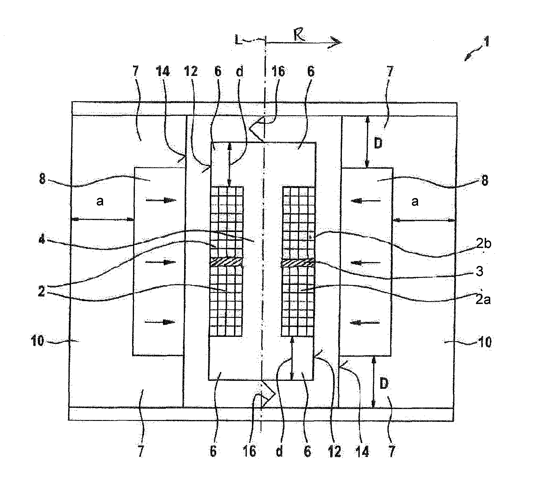
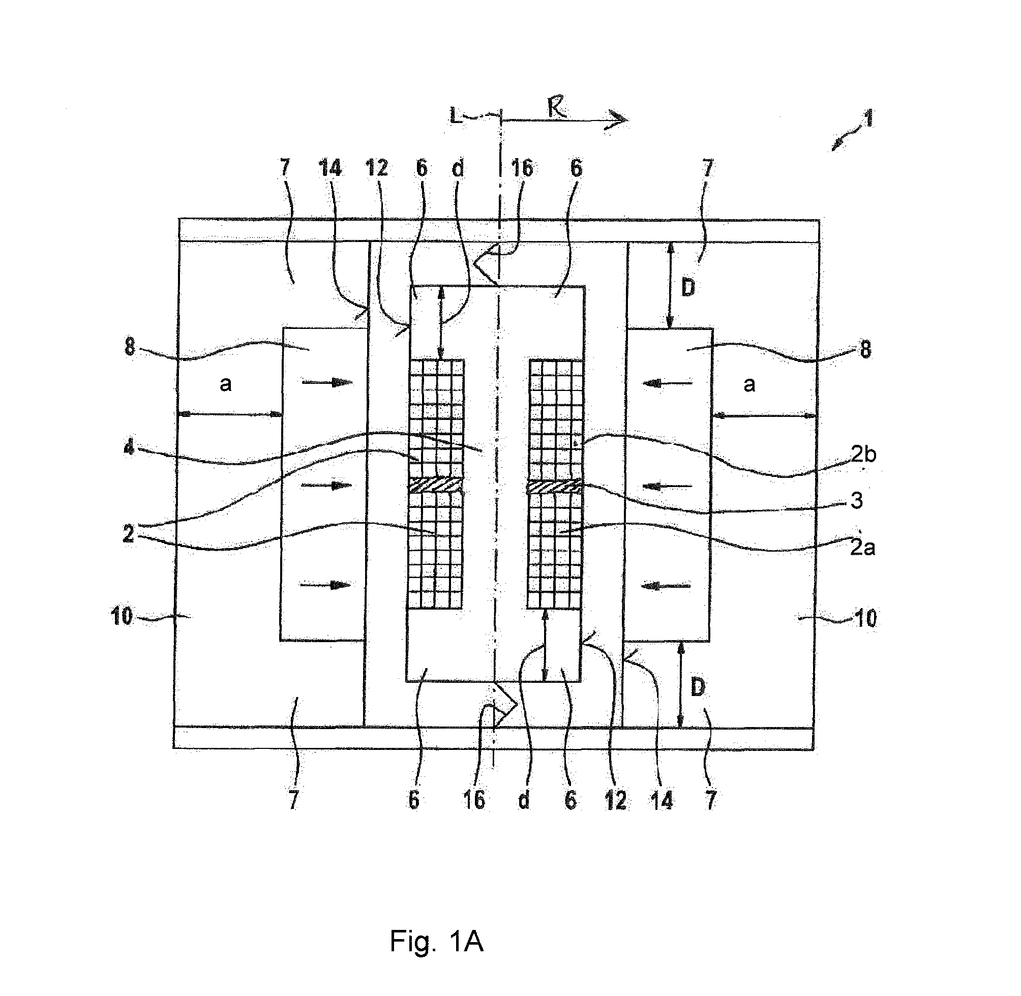
[0048]FIG. 1A shows a schematic cross section through an actuator 1 in accordance with the invention. The actuator 1 comprises at least one coil 2, which is wound around a first conducting element 4 and has a longitudinal axis L. The coil 2 is divided into a first, lower turns region 2a and a second, upper turns region 2b, wherein further subdivisions into more than two turns regions are also possible according to the invention. The first turns region 2a can also be considered to be a first coil 2a and the second turns region 2b can be considered to be a second coil 2b of a coil arrangement 2 or actuator coil 2.

[0049]The two turns regions (2a, 2b) can in this case, as illustrated by way of example in FIGS. 1A and 1B, be arranged spaced apart by a spacer element 3 in the axial direction with respect to the longitudinal axis L, which is not essential to the invention, however.

[0050]The first conducting element 4 protrudes beyond the coil 2 in the axial direction with respect to the lo...

second embodiment

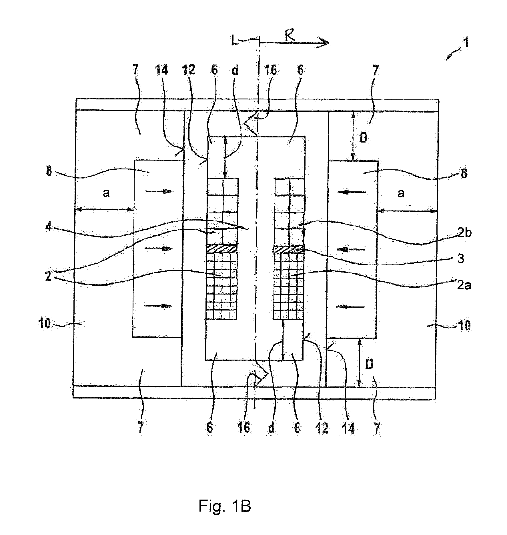
[0060]FIG. 1B shows a schematic cross section through an actuator 1 in accordance with the invention. In this preferred embodiment, the first turns region 2a of the at least one coil 2 has more turns than the second turns region 2b. For this, the turns of the first turns region 2a are designed to have a smaller cross section than the turns of the second turns region 2b. In addition, the turns of the first turns region 2a are fed or excited at a lower frequency than the turns of the second turns region 2b.

[0061]By virtue of this preferred configuration of the turns according to the invention and the feed to these turns, high forces can be generated in the actuator both at low and at high frequencies. Thus, for example, the first turns region 2a which, owing to the configuration of its turns, generates high forces even in the case of low-frequency current or voltage feed, with which high forces the low-frequency mechanical oscillations can be effectively reduced, can be used, for exa...


PUM

PropertyMeasurementUnit
outer diameter dAaaaaaaaaaa
angleaaaaaaaaaa
thicknessaaaaaaaaaa

Abstract

An actuator has an electrically conductive coil which has a longitudinal axis and a plurality of turns and a magnet arranged at a distance from the turns in radial direction relative to the longitudinal axis. The coil is partially covered by a central region of a first conducting element on a side which faces away from the magnet and the magnet is partially covered by a mid region of a second conducting element on a side facing away from the turns of the coil. The first conducting element projects beyond the coil and the second conducting element projects beyond the magnet in the direction of the longitudinal axis and there each have collar-like projections. The coil has a first winding turns region and a second winding turns region.

Description

CROSS REFERENCE TO RELATED APPLICATIONS[0001]This application is a continuation application of international patent application PCT / EP2012 / 064777, filed Jul. 27, 2012, designating the United States and claiming priority from German application 10 2011 053 289.7, filed Sep. 6, 2011, and the entire content of both applications is incorporated herein by reference.BACKGROUND OF THE INVENTION[0002]Such an actuator is known from U.S. Pat. No. 6,476,702, for example. This actuator has an electrically conductive coil, which has a longitudinal axis and a plurality of turns, and including at least one magnet, which is arranged spaced apart from the turns of the coil in the radial direction R with respect to the longitudinal axis L. The coil is at least partially covered on a side remote from the magnet by a central region of a first conducting element, and the at least one magnet is at least partially covered on a side remote from the turns of the coil by a central region of a second conducti...

Claims


Application Information

Patent Timeline
Patent Type & Authority Applications(United States)
IPC IPC(8): H01F5/00H01F7/08
CPCH01F7/081H01F7/13H02K33/18H01F7/11H01F5/00
Inventor GENDERJAHN, ROBERTPREUSSLER, STEFANKARKOSCH, HANS-JUERGENMARIENFELD, PETER-MICHAEL
Owner CONTITECH VIBRATION CONTROL
Why Eureka
Try Eureka